Have you managed to get (or fabricate) a schematic of this amp? Love to see how they are implementing the servo.
Have you managed to get (or fabricate) a schematic of this amp? Love to see how they are implementing the servo.
Not yet unfortunately.
The "relatively managable pain time" the last two days was spent measuring and matching sot-23 jfet's, one hundred of them.
Tomorrow I'll go for another MRI of my neck, so... maybe during the weekend. Not making promises though.
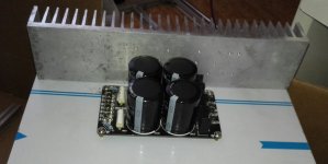
I had to get a different heatsink for this amp.
I think that will be sufficient for a pair of LM3886TF's.Heatsink size:
Length:300mm
Height:70mm
Thickness:40mm
Substrate thickness:7.5mm
Weight:about 1.3kg
Plenty. Might even do for three or four devices.
I'd rather go "too" big than not big enough 🙂
Another plus is that it can be used for something else should I not like the amp.
Here's a heat sink that's perfect for those LM3886 projects:
"Heat Sink size 6" X 8" X 1/2" great for use with the Alesis Modules--- $3.95"
Heat Sinks & Knobs
"Heat Sink size 6" X 8" X 1/2" great for use with the Alesis Modules--- $3.95"
Heat Sinks & Knobs
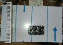
Recieved the two alu-sheets I'll use as bottom/top-plates on this amp... I wanted space to do a nice layout, and I got it lol.
The sheets are 500*300*3mm, and that's a bit larger having them in front of me than just looking at the measurements.
The idea is to use the 300*70*40mm heatsink as one of the side-panels, have something like dark oak for front-plate and the other side-panel.
I haven't decided on what to use as backplate/panel.
According to tracking info, the heatsink has made it to Sweden. Faster than expected, but that's great.
Now, it remains to be seen how long Swedish postal service sit on it before I recieve the package.
Now, it remains to be seen how long Swedish postal service sit on it before I recieve the package.
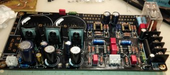
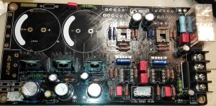
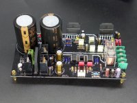
A 0-24Vac + 0-24Vac 500VA from toroidy and a total of 6 10000uF capacitors, of those 4 are on a board with rectifier diodes. Don't recall the model, they are TO-220 type diodes.
That's a LOT of capacitance! I like it!! I used two of these instead:A 0-24Vac + 0-24Vac 500VA from toroidy and a total of 6 10000uF capacitors, of those 4 are on a board with rectifier diodes. Don't recall the model, they are TO-220 type diodes.
380LX333M050A082 Cornell Dubilier - CDE | Mouser
as it was a little bit less $$ and smaller than 3 x 10,000uF. Have you considered a regulated supply like this?:
High current dual rail regulator kit for power amplifier or bench power supply ! | eBay
Last edited:
No, I have the other stuff mentioned.That's a LOT of capacitance! I like it!! I used two of these instead:
380LX333M050A082 Cornell Dubilier - CDE | Mouser
as it was a little bit less $$ and smaller than 3 x 10,000uF. Have you considered a regulated supply like this?:
High current dual rail regulator kit for power amplifier or bench power supply ! | eBay
I've not considered getting a different supply for this amp.
I`m watching how it goes. Well done ! I`m interested in as I have one kit on order.
I have an older LM3886 dc servo implementation which also has NE5534 as an input buffer or gain or something (I don`t know).
I have listened to this older one and I was very pleased. But I will do the new one too.
My questions:
As NE5534 is not unity gain stable and needs at least 3x gain then is this kit implementing such a gain? Maybe if I calculate well it is on 5x ?
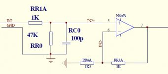
Is the 523 Ohm an input NE5534 resistor and if so should be matching the value of the gain setting resistors? I mean in the older one there are three resistors, RR1A, RR3A and RR4A where RR1A should be 1K based on the values of the other two, you can see the attached schematic of the old one. I don`t recall where I had read about it neither the calculation formula but back then I was looking at it I was convinced it must be 1K or there will be a DC offset. Am I right on this? Am I missing something?
Is the supplied regulator for the uPC1237 a 7824 and not a 7812 one or the stuffing drawing is false?
What is the lead spacing required for the 4.7uF input capacitors? Can you measure?
Is the 10R supposed to be 10R or 10K? (as there is no schematic)
I have an older LM3886 dc servo implementation which also has NE5534 as an input buffer or gain or something (I don`t know).
I have listened to this older one and I was very pleased. But I will do the new one too.
My questions:
As NE5534 is not unity gain stable and needs at least 3x gain then is this kit implementing such a gain? Maybe if I calculate well it is on 5x ?
Is the 523 Ohm an input NE5534 resistor and if so should be matching the value of the gain setting resistors? I mean in the older one there are three resistors, RR1A, RR3A and RR4A where RR1A should be 1K based on the values of the other two, you can see the attached schematic of the old one. I don`t recall where I had read about it neither the calculation formula but back then I was looking at it I was convinced it must be 1K or there will be a DC offset. Am I right on this? Am I missing something?
Is the supplied regulator for the uPC1237 a 7824 and not a 7812 one or the stuffing drawing is false?
What is the lead spacing required for the 4.7uF input capacitors? Can you measure?
Is the 10R supposed to be 10R or 10K? (as there is no schematic)
Attachments
Is there any progress on the build?
My kit arrived today, have not looked at it though. I`m a slow builder, the previous one is not finished yet...
But I would like to hear how it goes.
My kit arrived today, have not looked at it though. I`m a slow builder, the previous one is not finished yet...
But I would like to hear how it goes.
The heatsink arrived today.
Some pics attached The 3mm thick alu-sheet looks very big lol
Any update? I am thinking to get this kit. Please share your experience.
I will eagerly wait for your update. On the surface, the kit looks very nice. If it's as good sounding as it looks, it's worth the money I think.
NE5534 datasheet says:As NE5534 is not unity gain stable and needs at least 3x gain then is this kit implementing such a gain?
"The op amps are internally compensated for gain equal to, or higher than, three. The frequency response can be optimized with an external compensation
capacitor for various applications (unity gain amplifier, capacitive load, slew rate, low overshoot, etc.)."
It says that they are internally compensated for gains > 3; so use of an external capacitor in the compensation circuit is required for unity gain operation. NOT that they are unstable at unity gain.
- Status
- Not open for further replies.
- Home
- Amplifiers
- Chip Amps
- Is this a good LM3886 Kit?