Greetings,
i am not very skilled and i dont know alot about tube amp design,
im more into solid state. A friend of mine has an old chassis,
and on there he has 2x ECC83 an one 12AX7 and a sutible power transformer,
for filaments and the amp itself and a rectifier with smoothing caps and
a smoothing coil. There is also an output transformer with a centre tap on primary and on the secondary a speaker is connected.
Only trouble is, that there is no circuit 🙂
So he asked me if i could make a very simple low power amp.
So i looked on the net a bit and found a circuit and brief explanation in the link below. I would like to build a circuit #2, because its simple and i have almost all the parts.
So i ask you experts, is this circuit (#2 in the link) okay for general not very hifi listening?
And are there any errors?
EL84 Valve Amplifiers
It could be improved here and there but it is a nice beginners project.
Attachments
Last edited:
These are nice designs and some are even cute but are not for starters as the required transformers are not to get here easily or even have to be made (sure you can order them in Japan or far east but that is not what you do when you never build a tube amp before). A trafo for a PP EL84 is no problem (can be salvaged from an old amp) and the EL84 is a fine tube as well.
From Post #1, the 1st circuit was popularized in by the Dyna, the 2nd cct is 2/3rds of a Mullard 5-10 & the 3rd is a mutt used by many. All will give good service.🙂
A single O/P trafo suggests either mono or guitar. Guitar belongs on the Instruments and Amps "board".
12AX7 = ECC83. What rectifier tube is present on the chassis?
IMO, circuit #2 leaves much to be desired. Full pentode mode O/P tubes without NFB distort badly and exhibit a thoroughly miserable damping factor. 😡 Also, an interaction with Miller capacitance will roll HF info. off, at the circuitry's I/P. I suggest the Dyna ST-35 be looked at. Use 1/2 a 12AX7/ECC83 and 1/2 a 12AU7/ECC82 in each channel. The Russian 6H2Π (6n2p) is an excellent alternative for the voltage amplifiers bottle.
Attachments
I would choose circuit 3. It also has self bias for easier bring up. Phase splitter/driver that need less attention. Negative feed back circuitry for more stabilities. It properly has lower distortion and better low end (lower output impedance) than circuit 2.
Electronicsman,
From your limited description in Post #1, it seems that you want to build a low power amp for your friend, from the parts that you listed.
With only preamp and/or line amp tubes on that chassis, I bet it was some kind of preamp.
If the power transformer does not have enough current, it will not even be able to be used for a single ended EL84 Mono-block.
To build a low power amp, especially in stereo, requires a medium chassis, and a power transformer that has enough voltage and current.
You did not post any pictures, so there is not enough information of what you have.
Perhaps it is better to start from scratch.
Lots of circuits posted already.
Also, it would be helpful to know what kind of speakers your friend has.
High efficiency, low efficiency.
Background music listening, or a big party.
Low power to one may mean high power to another.
Mono, or stereo?
Signal source, a CD player, or a phono cartridge.
A music playback system is just that, a system.
Each part of the system puts requirements on the other parts of the system for it to play well together.
And yes, it is possible to build a low power amplifier that should please, depending on the other parts of the system.
The more we know, the more we can see what would be reasonable that will work as a system.
Describe the Target, and then aim to hit it.
Last edited:
#2 is an excellent, classic EL84 push pull tube amp design.
If you ask on a forum, you will get hundreds of answers and schemos for an amp, everyone will have a favorite.
But #2 is an all time, simple classis design.
Its quality comes from its parts, so buy good parts and you will have an excellent tube amp.
If you ask on a forum, you will get hundreds of answers and schemos for an amp, everyone will have a favorite.
But #2 is an all time, simple classis design.
Its quality comes from its parts, so buy good parts and you will have an excellent tube amp.
#2 is full pentode and no NFB. That's very bad. A 1 megohm grid to ground resistance on a 12AX7/ECC83 grid is a prescription for HF info. loss.
BTW, #2 is a paraphase setup and that topology is not currently viewed with favor.
BTW, #2 is a paraphase setup and that topology is not currently viewed with favor.
1. The 3 schematics of Post # 1:
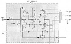
All 3 circuits are Self Bias designs. Great for simplicity, great for turn on ease, and great for being able to easily measure each output tube's current (I = V/R). The output transformer loves matched currents, to prevent early core saturation. Most self bias circuits have enough local bias DC feedback to make 2 tubes that are not real well matched to each other have reasonably similar cathode currents.
Circuit #2 has a 1 Meg Ohm input grid resistor. If the grid is not leaky; there is no problem with the large Miller Effect Capacitance . . . as long as the signal source output impedance is 50k or less.
Circuit #2, As far as the 2nd triode grid, the grid resistor is 1 Meg Ohm. As long as the grid is not leaky, that is OK. The large Miller Effect Capacitance is driven by 1 Meg Ohm, in parallel with 470k Ohm, in parallel with 470k Ohm. That is 190.3k Ohm. That may not be OK, So,
Calculate the (Miller Effect Capacitance +1C) to see where the -3dB rolloff is.
Then divide that frequency by 2 to find the -1dB rolloff frequency of that circuit.
I am not a fan of that kind of phase inverter, but it works reasonably well.
Circuit #2, as stated already in an earlier post does not have any negative feedback.
Pentodes need some form of negative feedback: Global, Ultra Linear, or Schade.
Global is often the hardest to adjust for good stability, especially with the large variation of output transformers. Usually a cap across the feedback resistor is needed, and needs to be adjusted to the proper value versus output transformer variables.
Then there either is the need for a dominant pole, or lack of need for a dominant pole at the first plates circuit (Series RC to ground). If needed, that RC has to be calculated too.
2. There are many more good circuits in the other posts of the thread.
Most of the Shishido circuits are not so much for an inexperienced beginner. Many are DC coupled, use grid current, use interstage transformers, or are otherwise more complex designs.
The other circuits are simpler, or more straightforward.
The main thing is the proper implementation of all of the circuits posted in this thread, and a good selection of parts that may have a major effect on the outcome, like output transformers sometimes do.
Either a UL transformer, or one that can easily be stabilized if Global negative feedback is used.
And another alternative is to use Triode wiring of the Pentode (EL84), or Triode wire a Beam Power tube (6BQ5).
Then, the Triode wired amplifier may work reasonably well without any negative feedback.
The above are just my opinions, which I put here alongside the other opinions.
3. It may be time to hear back from the original poster.
Last edited:
- Home
- Amplifiers
- Tubes / Valves
- Is this a good circuit for general listening