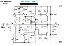
All the transistors have far lower Vce than required,
only the 140 V VCE output pair may survive the voltage,
BUT not the output power if ever it is used at full power
on a 4R load, or even unloaded, as the VBE multiplier
voltage drop is set with a fixed resistance divider which
is unrealistic given the transisors caracteristics dispersions..
only the 140 V VCE output pair may survive the voltage,
BUT not the output power if ever it is used at full power
on a 4R load, or even unloaded, as the VBE multiplier
voltage drop is set with a fixed resistance divider which
is unrealistic given the transisors caracteristics dispersions..
Last edited:
two pairs of MJ15003/4 on 70V power supplies is guaranteed to blow up when pushed hard.
All of the other transistors, BC557, BD139/140, BD243C/244C are also not capable of working on a total supply of 140V.
The circuit would work if you use say 35v supplies, but then you would not get 500W.
I wouldn't build it.
All of the other transistors, BC557, BD139/140, BD243C/244C are also not capable of working on a total supply of 140V.
The circuit would work if you use say 35v supplies, but then you would not get 500W.
I wouldn't build it.
I would have added a current mirror to the LTP.
Use MPSA42 and MPSA82 transistors as these can stand 150V easily.
I also would have added a safely wired pot to the Vbe multiplier.
Use MPSA42 and MPSA82 transistors as these can stand 150V easily.
I also would have added a safely wired pot to the Vbe multiplier.
Better to find a design already made for it, than try to modify one that isnt
Besides, 500W into 8 ohms is not really DIY - you will pay more to build it than you will to buy it.
Besides, 500W into 8 ohms is not really DIY - you will pay more to build it than you will to buy it.
- Status
- Not open for further replies.
- Home
- Amplifiers
- Solid State
- Is this a bad scheme