Anyone with a bizarre, unknown, corrupted, misused, failing, whatever application of this circuit (or a 'Vgs-multiplier'), high frequency related, oscillator or modulated contraption, or whatsoever unthinkable of, I would like to know what is in the sleeves of you electronic designers garments and knowledge.
But please I beg, no explanations of how those circuits operate or what there used for. Just the circuits. Nothing more
This is part three and will be wrapped up at the closing of '23.
The former two went beserk (link,link,).
But please I beg, no explanations of how those circuits operate or what there used for. Just the circuits. Nothing more
This is part three and will be wrapped up at the closing of '23.
The former two went beserk (link,link,).
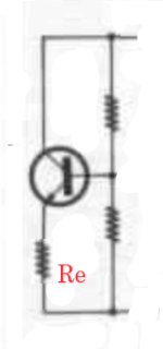
The circuit of the "Vbe" multiplier also works as an impedance multiplier of re,
or re+Re, or re+Ze, where Ze will be a complex combination of R, L, C. -whatever
is connected between Em. lead and the lower resistor in the base divider.
The multiplier is the same as for the voltage.
or re+Re, or re+Ze, where Ze will be a complex combination of R, L, C. -whatever
is connected between Em. lead and the lower resistor in the base divider.
The multiplier is the same as for the voltage.
Thanks StevenOH!
I've never heard / seen such a circuit. Can you provide an example / post a picture? A rough sketch is fine.
I've never heard / seen such a circuit. Can you provide an example / post a picture? A rough sketch is fine.
Still doing prior art searches via a public forum?
Anyway, a VBE multiplier is used as part of a low-voltage bandgap reference inside the LM10, see
https://www.ti.com/lit/ds/symlink/lm10.pdf
Q72 in Fig. 71.
Anyway, a VBE multiplier is used as part of a low-voltage bandgap reference inside the LM10, see
https://www.ti.com/lit/ds/symlink/lm10.pdf
Q72 in Fig. 71.
Last edited:

Yes, just to know my application has not been covered in the past or is still valid in the present.
It does not exist, or is not to be found. Not on the net, not in the libraries. Nowhere.
So given all the responses sofar, I'm pretty safe to have my application 'claim free'.
Thanks for the provided bandgap pdf. Always nice reading into those electronic depths.
pm
It does not exist, or is not to be found. Not on the net, not in the libraries. Nowhere.
So given all the responses sofar, I'm pretty safe to have my application 'claim free'.
Thanks for the provided bandgap pdf. Always nice reading into those electronic depths.
pm
The first attach depicts inclusion of Re for (re+Re) multiplication.
Or any other combination of R, C, L to be amplified (as will be seen between output leads).
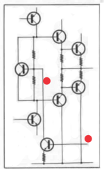
The second attach shows one of the methods to allow for the manipulation of the bias to
achieve Sliding bias cl.A, or Non-switching cl.AB...
Or any other combination of R, C, L to be amplified (as will be seen between output leads).
The second attach shows one of the methods to allow for the manipulation of the bias to
achieve Sliding bias cl.A, or Non-switching cl.AB...
Attachments
Another example is Clarion patent:
https://worldwide.espacenet.com/pat...4031/publication/JPS5912604A?q=pn=JPS5912604A
https://worldwide.espacenet.com/pat...4031/publication/JPS5912604A?q=pn=JPS5912604A
Yes, just to know my application has not been covered in the past or is still valid in the present.
It does not exist, or is not to be found. Not on the net, not in the libraries. Nowhere.
Most patent lawyers would be afraid that you unintendedly give away clues what your invention is. I don't think you have done so, though.
So given all the responses sofar, I'm pretty safe to have my application 'claim free'.
Thanks for the provided bandgap pdf. Always nice reading into those electronic depths.
pm
Have you seen the last post of your VGS multiplier thread? Andersonix did find a commercial circuit using it.
https://www.diyaudio.com/community/threads/vbe-vgs-multiplyer-with-mosfets.406414/post-7531875
It looks like a 'Vbe multiplier' is used as a non-linear load here to lower the distortion of the stage.Another example is Clarion patent:
https://worldwide.espacenet.com/patent/search/family/014844031/publication/JPS5912604A?q=pn=JPS5912604A
Does anyone know whether that works?
Jan
I haven't read the patent, I only looked at the schematic. It looks like a variant of the voltage mirror, where you would use a stack of n diode-connected transistors (and a resistor with value nRE if the common-emitter stage has an emitter degeneration resistor with value RE) if you want a gain of -n.
A voltage mirror works well as long as the load impedance is much higher than the impedance of the stack of diode-connected transistors (and resistor, if applicable). Too low load impedances disturb the distortion compensation.
In this variant, the voltage divider of the VBE multiplier will already disturb the distortion compensation. Maybe you can correct for it to some extent by using unequal voltages across the emitter resistors.
That second circuit is a form of positive feedback.The first attach depicts inclusion of Re for (re+Re) multiplication.
Or any other combination of R, C, L to be amplified (as will be seen between output leads).
The second attach shows one of the methods to allow for the manipulation of the bias to
achieve Sliding bias cl.A, or Non-switching cl.AB...
I would be very wary to use that; if it isn't exactly right it either doesn't work or, worse, will runaway and release the magic smoke.
Jan
I've sorted that out already. A publication (book) is the best option. Looking for a publisher now.Most patent lawyers would be afraid that you unintendedly give away clues what your invention is. I don't think you have done so, though.
Yes I saw Andersonix' post.
I've sorted that out already. A publication (book) is the best option. Looking for a publisher now.
Yes I saw Andersonix' post.
You mean you don't want a patent, but want to make sure no-one else can patent it either? After publishing, it is in principle part of the state of the art and no longer patentable, although there are apparently some temporary exceptions to that for the person who wrote the publication.
A patent will be very diifcult, as the idea is suitable for almost every circuit.
Diff pair, CM, cascode, and the two named after their inventors, Darlington and Sziklai. That level.
Diff pair, CM, cascode, and the two named after their inventors, Darlington and Sziklai. That level.
all stax solid state amplifiers use vbe multipliers as tail loads to generate the output stage bias.
Can you provide a circuit drawing?as tail loads to generate the output stage bias
This post by StevenOH kept buzzing in my head for over a year, that very last sentence.The circuit of the "Vbe" multiplier also works as an impedance multiplier of re,
or re+Re, or re+Ze, where Ze will be a complex combination of R, L, C. -whatever
is connected between Em. lead and the lower resistor in the base divider.
The multiplier is the same as for the voltage.
Today I received a fierce spark in the processing unit: also vice versa.
If your not in math, just notice the boiled down conclusion in the magenta rectangle at the bottom.
Attachments
not sure if i understand what you're asking...
in my day job about 8 years ago, i needed to replace a high voltage zener diode in a xenon tube strobe design that I was asked to "cost reduce". The zener was expensive anyway but became much more so when the primary supplier put it on the NRFND list. Then, my usual 2nd source suppliers dropped the part. I ended up using a VBE multiplier circuit to act as a much cheaper replacement for the high voltage zener. Worked great!
in my day job about 8 years ago, i needed to replace a high voltage zener diode in a xenon tube strobe design that I was asked to "cost reduce". The zener was expensive anyway but became much more so when the primary supplier put it on the NRFND list. Then, my usual 2nd source suppliers dropped the part. I ended up using a VBE multiplier circuit to act as a much cheaper replacement for the high voltage zener. Worked great!
- Home
- Design & Build
- Electronic Design
- Is there any other know use of Vbe multipliers... other then Vbe multipliers?