I hesitate to build a project where the internal dimensions are too close for comfort. It just poses a problem that doesn't need to become something from nothing. I agree with the idea of space being the less expensive option with a one chassis project, yet in the case where i know that a circuit is going to have issues with hum as a given, then a two chassis solution will give much less frustration in the build in the first place.
If two chassis is out of the question prepare yourself for much experimentation. Mu-metal has served me well, but not completely and it was like building a chassis within a chassis.
As a question, can someone tell me whether it is needed to use Mu-metal beneath a transformer as well? My guess is that when the transformer is directly mounted to a steel chassis, the field may be extended by the chassis as well?
As Tom indicates previously, you really need to close the loop to shield against magnetic hum. A box or ring is best. My experience in industrial stuff is mu-metal is great, but annealed soft iron works nearly as well in many cases. Now, here's a weird thing. If you can get a 5/8" thick slab of 6061 aluminum and just place it between the transformer and circuit, it may well attenuate hum as well as anything. Has to do with eddy current losses and 1/2" isn't nearly as effective. Also, and especially for E-core transformers, don't feel bound to aesthetics. You can often get lower hum just by mounting the board or device at an angle, not square to the chassis.
If you can get a 5/8" thick slab of 6061 aluminum and just place it between the transformer and circuit, it may well attenuate hum as well as anything.
@Conrad Hoffman : I am pleased to see that someone - like me - had made the real experiment to discover this : Aluminium IS effective against any stray field, magnetic and others, if used suitably...
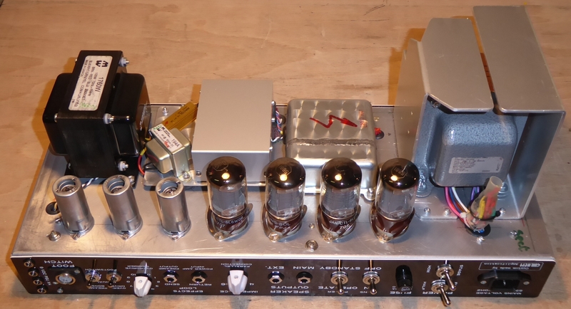
Below one of my DIY guitar amps - a dual-channel Hi-Gain model - where you can see Aluminium "wings" cutting the main magnetic radiation directions of the EI power transformer :
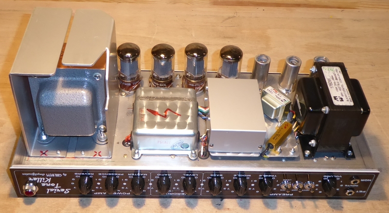
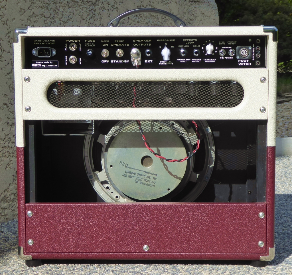
No more magnetic (or other) influence of any kind on the chassis, circuits, plugged-in guitars and EVM12L combo loudspeaker :
Before that, I originally installed two Toroidal transformers... The first unshielded, only with an OEM ribbon around the winding, and the second shielded by a Steel cover and aluminium base :
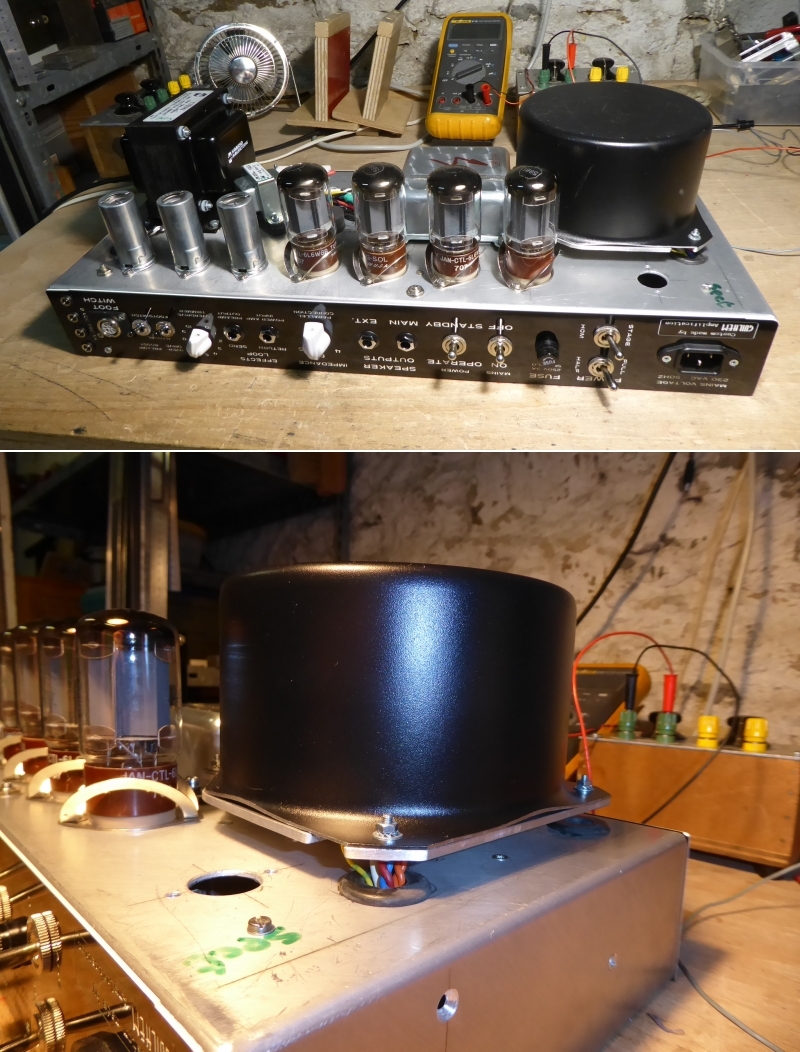
No way in both case : the amp was simply not usable. Just a poor improvement was noted with encasing the 2nd Toroïd here... Changing to EI plus adding the Aluminium "wings" settled all hum / buzz / spikes and other transformer adverse noises. Merci, au revoir ! 😎
T
Why not just wind a few layers of mu-Metal strip around the transformer. Besides those ferrite lumps around the cables do nothing, it needs to at least have one turn of wire through them, also they are for RFI not 50Hz. Copper/aluminium is the worst magnetic screen available, if you cannot find mu-metal then at least mild steel. Toroidal transformers are made from a flat strip of mu-metal (or at least close to) if you have an old trafo laying around you can use that as screening. Also don't bond the mu-metal screen to the chassis. If you have a piece of mild steel sheet lying around just stick it between transformer and amp to see the effect of it. Or as previously suggested swing the transformer on its side and see if that helps, that may be another solution.
I am currently working on a tube-based preamp in which 2 separate transformers are to be used. For both transformers, I enclosed them in one of those metal cans, plus under the can, there is now Mu-metal on the bottom. In addition to that, there is a low wall of mu-metal attached to wood. I realize now that this may or may not be effective, so it will all be revealed when the project is being tested. That is a ways down the road.

Last edited:
If I understand what you are asking, then they are oriented on the horizontal plane, parallel with the bottom of the chassis.
If that’s the case, the stray field from the bottom half of the EI will be attenuated but not the top half. If the wings were closed at the top, the attenuation would be even better because the top half loop would be closed. Consider on the bottom half, the field comes out to the left about halfway up from the mounting plate and then wrap’s around through the lower half of the wing and the chassis metalwork and then to the other wing where it closes the loop with the core.
For the Toroïd below, the main radiating field is out the sides perpendicular to the axis, so that would easily couple into the tube next to it. You could reduce this by adding a GOSS band, but my feeling is you’d still get some coupling due to the very close proximity. The idea of the GOSS band is the stray field from the transformer sets up a current in the band that is opposite in phase to the source, hence an opposing field in generated that cancels the original field. These usually work remarkably well and you get 20-30 dB stray field reduction on a good implementation.
You cannot make blanket statements about one type of trafo being better than another IMV without carefully considering layout and orientation. In the amplifier below, the toroid is very close to the tube and any stray field will easily modulate the electron flow from cathode to anode.
All things being equal though, a toroid is by far the quieter of the two types and that’s a generally accepted view amongst professionals that are expert in this, and my experience as well.
YMMV.

Bonsai,
Funny thing that you mentioned the GOSS band, as I was wondering to myself there were such a product. I would like to consider adding such a product in some of my builds. Where might I find a source for one?
Funny thing that you mentioned the GOSS band, as I was wondering to myself there were such a product. I would like to consider adding such a product in some of my builds. Where might I find a source for one?
Is it worth adding an ungrounded mumetal shield around my transformer then?
The transformer is an o-ring, which has been potted in the case you see.
There is absolutely no trace of hum, so it seems like a fix for something that is not there. I am just wondering if it may improve the sound quality.
The transformer is an o-ring, which has been potted in the case you see.
There is absolutely no trace of hum, so it seems like a fix for something that is not there. I am just wondering if it may improve the sound quality.
Hi, they usually get it put on during the manufacture of the trafo, but I think you could install one if you do it carefully. It to be tight around the outer edge over the full height and slightly folded over the top and bottom edges. It has to be fully conductive so they are spot welded in 3 or 4 places where the band overlaps.
Unfortunately I have no experience using a metal cover with a toroid, so someone who has tried this on the forum will have to comment.
What I can tell you is a c. 5VA RS potted VI transformer produced much more stray field than a professionally wound 1.2 kVA transformer (Tiger Toroids) fitted with a GOSS band and running at about 20% lower flux density than usual for the core material used. The stray field coming out the top of the EI core is a serious issue if you are trying to get low noise so orientation becomes very important. I had exactly the same problem with a beautifully made Hammond PCB mount EI transformer when I built my Symphony preamp back in 2013. I eventually had to go for a Talema toroid.
@Bonsai : If it did not worked, I would not relate it...
I made experiments to check what my colleagues at the ALSTOM Transformer Division suggested to me, to solve my induction issue, and it proved to be successful.
No "generally accepted views", nor "blanket statements", but facts, instead of your all around expert discourse.
T
I made experiments to check what my colleagues at the ALSTOM Transformer Division suggested to me, to solve my induction issue, and it proved to be successful.
No "generally accepted views", nor "blanket statements", but facts, instead of your all around expert discourse.
T
There are specific reasons why you got lower noise in your amp going for the parts and screening you did that can be explained logically by applying rudimentary EM principles. Placing a very large toroid near a tube is going to cause problems and replacing that with a much smaller EI trafo with the stray field oriented away from sensitive pickup points are the reason you got better noise. Your lower wing uses thick aluminium and very effectively closes the lower EI stray mag field, so the field is effectively trapped.
Like for like, there is no way an EI trafo quieter than a toroid.
Like for like, there is no way an EI trafo quieter than a toroid.
The O-core transformer was made by James Transformers, so I am pretty sure it is not very "noisy".Hi, they usually get it put on during the manufacture of the trafo, but I think you could install one if you do it carefully. It to be tight around the outer edge over the full height and slightly folded over the top and bottom edges. It has to be fully conductive so they are spot welded in 3 or 4 places where the band overlaps.
Unfortunately I have no experience using a metal cover with a toroid, so someone who has tried this on the forum will have to comment.
What I can tell you is a c. 5VA RS potted VI transformer produced much more stray field than a professionally wound 1.2 kVA transformer (Tiger Toroids) fitted with a GOSS band and running at about 20% lower flux density than usual for the core material used. The stray field coming out the top of the EI core is a serious issue if you are trying to get low noise so orientation becomes very important. I had exactly the same problem with a beautifully made Hammond PCB mount EI transformer when I built my Symphony preamp back in 2013. I eventually had to go for a Talema toroid.
I will give the mumetal a miss, unless I encounter a problem.
There is quite some difference between EI trafos. The cheap potted ones from RS and Block for example are very noisy. I had a Marantz PM7000 with an EI that had an external copper band designed to trap stray fields and it was not too bad. But, as I said before, all things being equal, toroids are remarkably quiet.
😊
😊
If that distance involves increasing the enclosure size, then its usually the other way round, shielding wins...Distance beats shielding on price any day of the week.
Tom
I meant distance within the same enclosure.
And, sure. You can always take a statement like "distance beats shielding on price" and distort it out of proportion. If distance means buying a house the next town over so you can put the power supply there, I'm pretty sure shielding will be lower cost. Common sense applies. 🙂
Tom
And, sure. You can always take a statement like "distance beats shielding on price" and distort it out of proportion. If distance means buying a house the next town over so you can put the power supply there, I'm pretty sure shielding will be lower cost. Common sense applies. 🙂
Tom
Well I thought you meant the physics of power (of interference) attenuates by the square of the distance. Obviously not something you understood when making the comment. But that is the cheapest and most lucrative solution.
I think its a bit more complex than square of the distance.
Surely its cube of the distance for near-field(*) (dipole source), square of distance for far-field (or near-field monopole source, though that's unusual). But those are power ratios, for voltage or current its the square root of those. This ignores orientation however, which can be key (for instance in reducing transformer coupling to other circuit loops).
Near field here means more than the dipole dimensions, so "nearish". And near field extends to infinity technically, its just going to be swamped by far-field at some point and become irrelevant. The transition to far field depends on the frequency/wavelength, for audio the em wavelengths are large and far-field isn't usually relevant.
- Home
- Design & Build
- Construction Tips
- Is there any benefit in adding an aluminium shield in my phonostage?