I will not be surprised to see them as outputs as they are rated at 8 Amp.
Base stopper resistors of 22R and CB caps of 47pF are used in Honey badger amp to stop oscillation.
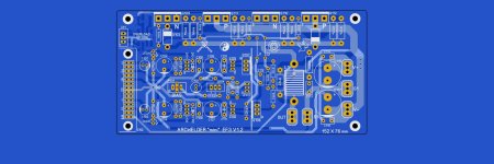
By the way, attached is the latest revision I could find for the Honey Badger amp.
Base stopper resistors of 22R and CB caps of 47pF are used in Honey badger amp to stop oscillation.
By the way, attached is the latest revision I could find for the Honey Badger amp.
Attachments
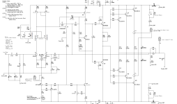
in that honey badger cct, there is 100nF in parallel with the 220uF feedback cap (C3)
is it worth to bypass the 220uF? what are the benefits?
is it worth to bypass the 220uF? what are the benefits?
Input and feedback networks are the whole topic of discussion.
From my simulations I can tell that two DC blocking capacitors do add to distortion.
I bypass them just to see true THD figures of the amplifier.
Or another way is set them high so they don’t add any distortion.
As example, I had input cap at 100uF and feedback cap at 1000uF. Simulated distortion was at 0.000150s. Bypassing caps showed distortion of 0.000080s
I’m going thinking about overbiasing output devices at 400mA or so to eliminate crossover distortion completely up to say 5W of power outputGreat stuff!
A suggestion: since a lot of the Blameless concept is about crossover distortion, have you done any investigating into this aspect (for example, distortion figures for mid to high frequencies at low output levels - maybe 10mW or similar)?
0.4A of static bias means the output stage leaves class-A when >= 0.8A peaks are delivered to the load (i.e. the speaker). A peak current of 0.8A on a sine wave is an RMS current of 0.566A. Power delivered to an 8 ohm load resistor is 0.566 * 0.566 * 8 = 2.56 watts. So your proposal exits class-A at two and a half watts (into an 8 ohm load).
Have some fun by re-running the calculations assuming 0.56 amps of static bias instead.
Have some fun by re-running the calculations assuming 0.56 amps of static bias instead.

It looks like it does.When approaching full power how does the 2nd Gain stage or Vas not swing close to 74 volts
Replaced VAS transistors with BSP43/33 as they are rated at 80V.
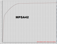
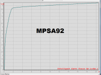
Right now I am also working on mostly SMT Blameless. I think I am going to use PZTA42T1G/PZTA92T1G for VAS and source.
Cool , another SMD SOT-223 VAS choice with higher Vce (300V). The 160V choice is 2SC3649-SA1419 , higher Ft , Hfe , and low Cob.I think I am going to use PZTA42T1G/PZTA92T1G for VAS and source.
OS
Yes , they would not be my first choice....
That's why I use <70V rails and 2SC3649-SA1419. And TO-126 - TTC/A004 , 006/011.
I've had to do a lot of "shopping" to enter the SMD world. Many of our beloved
linear semi's of the 20'th century are either obsolete or hard to source.
"SMD world" has kept the classic FJV1845/FJV992 alive ! I've spent time looking at data sheets.
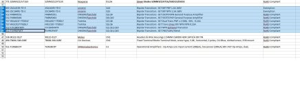
Below is a typical BOM for a 2020 input stage.
Many SMD replacements spec out better than their through-hole counterparts.
PS- not sure of the MPSA's , never used them.
That's why I use <70V rails and 2SC3649-SA1419. And TO-126 - TTC/A004 , 006/011.
I've had to do a lot of "shopping" to enter the SMD world. Many of our beloved
linear semi's of the 20'th century are either obsolete or hard to source.
"SMD world" has kept the classic FJV1845/FJV992 alive ! I've spent time looking at data sheets.
Below is a typical BOM for a 2020 input stage.
Many SMD replacements spec out better than their through-hole counterparts.
PS- not sure of the MPSA's , never used them.
Attachments
You are right. Douglas Self mentions on p.169 that "MPSA42 requires an unusually high Vce to work properly". In simulation, however distortion with PZTA42 was slightly smaller than with KSC3503. I guess I better swap back to 3503. Thanks!
This is a "Blameless" thread ??
OK -
(2009) 1st gen - "badger" from the archive .... (below) Good , but limited by it's EF2.
(2015) 2nd gen - "Wolverine" (original simulation) . EF3 was a good upgrade.
(2023) 3rd gen - (blameless) Infidel with Cascoded VAS.
Hard to beat the "blameless" in the simplicity vs. performance category. 3rd gen just has 4mA VAS- cool running SMD
changes. TPC and TMC options , still 2-5PPM THD.
SMD is cheaper , 9$ input stages.
OS
Attachments
SMD ? 2SC3649-SA1419 or FTZ796/696 , real high Ft , but 12pF Cob. FTZ's have 200+ Hfe. Hard to find 3503 (F) binnings.I guess I better swap back to 3503
Mouser only has 3503(D). Whatever's left... going , going .... gone.
OS
I do not mind two more TO-126s. Yes, only 3503D is available. Is high beta of 3503 in case of EF VAS important? I like your designs, but I am trying to build 6 channel amp with DSP, so size does matter. Wolverine is HUGE!
The hfe of the 3503/1381 (D) is in a beta enhanced VAS , just use a higher gain beta device. A P/N match is not critical , since one device isI do not mind two more TO-126s. Yes, only 3503D is available. Is high beta of 3503 in case of EF VAS important? I like your designs, but I am trying to build 6 channel amp with DSP, so size does matter. Wolverine is HUGE!
a CCS , the other is the Darlington pair... Symmetric designs , it DOES matter.
Why not just use the TTA/C004 ? Mouser has the "B" TTA/C ( 20K stock). 250Hfe. Unless you are running >80 rails . Small amps = <60V ....
Edit - or use those 2 SMD devices I mentioned .. Good or better for <70V.
I'm building small ones ,as well.
https://www.diyaudio.com/community/...smd-60w-amps-wolverine-compatible-ips.398785/
First post is now at 6 complete PCB's with BOM (2 IPS's and 2 output stages).
"Mini" (below) is a 4 device 100W. Modular like Wolverine. I use a 2 X 14 cable to connect IPS/OPS. My 4 channel will have all 4 IPS's right at the back
panel. Protection opto is also integrated. Fuses are on the matching DC PCB.
OS
Attachments
How about BF722/723?Cool , another SMD SOT-223 VAS choice with higher Vce (300V). The 160V choice is 2SC3649-SA1419 , higher Ft , Hfe , and low Cob.
OS
I'll have bookmark that one , 60Mhz Ft / 2pF Cob / 250V. Mouser has lots of them ! Wow , that is low Cob (1.6pF)BF722/723
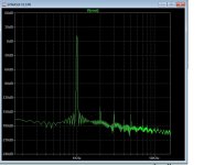
Oh , there is one "blameless" That truly shames all the others (below).
And that is not a "glitch". Distortion magnifier might have a problem with this one .... simple ,too.
I'll buy the BF's for these IPS's. Semi "defects" would be the only distortion mechanism with this circuit.
OS
Attachments

- Home
- Amplifiers
- Solid State
- Is there a simple one-to-one simulation for Blameless amplifier in LTspice?