Is there a semi-triode mode for pentodes, between the normal pentode configuration, and the conversion of the pentode to a triode by strapping G2?
I am directed down this path by three observations:
1. Several blogs point out that a pentode can be converted to a triode by disconnecting the anode and using G2 as the anode. They state there is no advantage in doing so, but it is possible.
2. Many data sheets show G1 and G2 current when the anode voltage is taken below G2 voltage. I cannot imagine that the tube manufacturers would have wasted paper printing these curves unless there was an application.
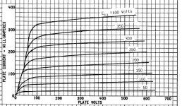
3. Many data sheets show pentode load lines becoming very slightly more vertical as G2 approaches anode voltage. Does this pattern continue as G2 exceeds anode voltage? If so would the load lines approach the vertical load lines of triodes? (This could be pursued by reducing anode voltage rather than increasing G2 voltage to respect voltage ratings)
Obviously the output of the tube would plummet as anode voltage is taken below G2, but we already accept that when we triode-strap them. If the anode is not taken too far below G2 does the valve enter a semi-triode mode of reduced power and lower distortion? If so can anyone provide links to descriptions of such regimes?
To take this heresy to another level, could we take the semi-pentode signal from G2 rather than the anode? If we plot a 2K Ohm load line on the G2 current curve rather than the plate current curve we find a very linear region with bias of -12V and B+ of 80V and G2 at 250V if we limit the G1 voltage swing. Admittedly the voltage gain is only 1.5, and the power .2 W, but it might make a good headphone amp by taking G2 to 400V?
Obviously we would not pursue a high load as at an 8K Ohm load the -8 volt bias line crosses the load line four times...
And the curves are mirrored, so the valve no longer inverts phase of the input?
I am directed down this path by three observations:
1. Several blogs point out that a pentode can be converted to a triode by disconnecting the anode and using G2 as the anode. They state there is no advantage in doing so, but it is possible.
2. Many data sheets show G1 and G2 current when the anode voltage is taken below G2 voltage. I cannot imagine that the tube manufacturers would have wasted paper printing these curves unless there was an application.
3. Many data sheets show pentode load lines becoming very slightly more vertical as G2 approaches anode voltage. Does this pattern continue as G2 exceeds anode voltage? If so would the load lines approach the vertical load lines of triodes? (This could be pursued by reducing anode voltage rather than increasing G2 voltage to respect voltage ratings)
Obviously the output of the tube would plummet as anode voltage is taken below G2, but we already accept that when we triode-strap them. If the anode is not taken too far below G2 does the valve enter a semi-triode mode of reduced power and lower distortion? If so can anyone provide links to descriptions of such regimes?
To take this heresy to another level, could we take the semi-pentode signal from G2 rather than the anode? If we plot a 2K Ohm load line on the G2 current curve rather than the plate current curve we find a very linear region with bias of -12V and B+ of 80V and G2 at 250V if we limit the G1 voltage swing. Admittedly the voltage gain is only 1.5, and the power .2 W, but it might make a good headphone amp by taking G2 to 400V?
Obviously we would not pursue a high load as at an 8K Ohm load the -8 volt bias line crosses the load line four times...
And the curves are mirrored, so the valve no longer inverts phase of the input?
Attachments

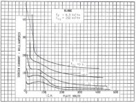
Those screen current curves are the resulting screen current if the plate and control grid voltages move around in a standard pentode-connected circuit. So you are proposing connecting a load to the plate of a pentode and then taking the actual circuit output from the screen? It is about the most inefficient way to use a pentode possible. And it isn't all that linear.
If you are looking for something between a triode and a pentode, you should just do a little voltage feedback on a pentode. Then you get the awesome efficiency of a pentode and the linearity of a triode 😎 (much better actually if you apply enough feedback).
If you are looking for something between a triode and a pentode, you should just do a little voltage feedback on a pentode. Then you get the awesome efficiency of a pentode and the linearity of a triode 😎 (much better actually if you apply enough feedback).
From plate to grid?do a little voltage feedback on a pentode
How about Crazy Drive? Or is this just for VAS and not appropriate for an output stage?
From plate to grid?
How about Crazy Drive? Or is this just for VAS and not appropriate for an output stage?
Any type of voltage feedback, whether series or parallel applied. They have equivalent effect, but affect the driving stage differently.
Crazy Drive still has a pretty high resulting plate resistance, though the linearity is astounding.
It really depends on what you want to accomplish, what you mean by "semi-triode." If you want low plate resistance, Crazy Drive might not be what you are looking for. If you want better linearity with still high-ish plate resistance, it might be exactly what you are looking for. Choose the configuration that gives what you want.
I've made high-swing drivers with CCS-loaded pentodes with plate-grid feedback via a resistor that have orders of magnitude less distortion than any triode I have ever tested or heard of. I've also made two amps with pentodes and voltage feedback, one with 30% plate-grid feedback via resistor, the other 50% voltage feedback in a cathode feedback winding. Both sported much better performance than a typical 300B output stage. It turns out that pentodes make the best triodes.
...Obviously the output of the tube would plummet as anode voltage is taken below G2...
Obviously it does NOT. These are not True Tetrodes. G3 shields P from G2. P may go to about 20% (10%-30% depending on tube) of G2 before current "plummets".
This happens all the time in Power Amps, and also many Voltage Amps driven to high level.
The point is that G1 and G2 currents ARE dependent of the PLATE voltage: as long as it is high enough to attract electrons, they cross the grids without landing on and the grids currents are low.. . .
2. Many data sheets show G1 and G2 current when the anode voltage is taken below G2 voltage. I cannot imagine that the tube manufacturers would have wasted paper printing these curves unless there was an application.
. . .
You may also note than the sum of the plate and the G2 currents is almost constant.
When plate voltage is 0, the G2 usually blows.
Look at:
http://www.dissident-audio.com/OutsideDocs/RCA_1938_BeamPowerTubes_TechPapers.pdf
Yves.
P.S.
And since G2 current is "modulated" by plate voltage, some have used the plate as input and the G2 as output !
Last edited:
Internal fields in the tube cause internal feedbcks that make curves more vertical. Screen grid shields the feedback, but not absolutely, the effect is voltage dependent, hence non-linear.
The best way to straighten them is to use plain, linear external resistive dividers.
The best way to straighten them is to use plain, linear external resistive dividers.
It is an opposite thing, to linearize the internal feedback, making it more pentode-ish.How about Crazy Drive? Or is this just for VAS and not appropriate for an output stage?
Is there a semi-triode regime for pentodes?
Active Ultralinear:
https://www.diyaudio.com/forums/tubes-valves/98330-people-dislike-ultralinear-8.html#post1176732
Uses a differential tube pair as an Op Amp to control the screen grids of the output tubes so as to get a constant Mu. Could use a 6BN11 or 8CB11. (on the $1 list)
Attachments
- Home
- Amplifiers
- Tubes / Valves
- Is there a semi-triode regime for pentodes?