Dear experts,
I need your kind help and knowledge for understand if I’m on the right path or not. I’m doing a 3 way project MTMWW (SB 26ADC-C000-4, 2xTB w4-1337sd, 2xRCF L8S800). The idea is use an active XO (miniDSP 2x8) and 3 Crown XLS for run the drivers.
For the measurements, I have a UMIK-1 and an external sound card.
Here the simulation of the active XO based on the in box measurements (minimum phase)
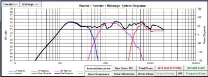
After several nights of study, I’m still not sure I’m doing the right thing, and I would to know your opinions on the below
Question #1 – real time delay
I’m struggling to understand if there is a way to correctly measure the driver time delay: I’m using the methodology from “Finding the Relative Acoustic Offset in PCD” written by Jeff Bagby, but I would like to measure the result back to see if the drivers are really aligned after input in the MiniDSP the simulated delay. Can you please help me, or point to some tutorial? Is that possible?
Question #2 – phase alignment
I’m not sure I’ve understand yet the driver time alignment, and when they look good or not. In my simulation excel (Passive Crossover Designer 7 (2007)) I can get the phase – or at least I think so – but I’ve no idea if they are right. Below the results
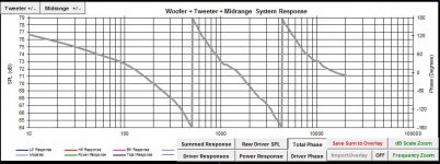
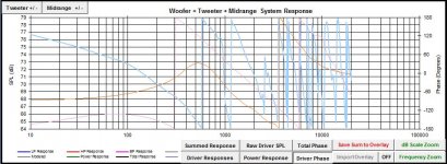
All the measurement are “minimum phase” before the simulation
Can you please give me your comments or, again, point me to some “good phase” and “bad phase” alignment example, so maybe I can finally get it?
Question #3 – standing waves
I have done all the inbox measurement, and looks like nothing is wrong from the impulse and FR point of view, and I can’t hear anything strange when I run the sweep.
Is there any example or clear way to define if there are or not standing waves, and how to identify them?
Question #4 – protect the tweeter
Do I need to protect the tweeter? I will probably use a 2nd order filter at 4000kHz, is it still necessary? I can even use the amp capability to work as a low pass filter as safety net.
I would really avoid to add any passive components, because a 47uF capacitor in series it’s, at the end, a 1st order filter…
All the FRD, Impulse response, Phase, ZMA in box measurements available: I didn’t bother you with 16 pics yet 🙂
Thanks to all that will find the time to answer!
cheers
I need your kind help and knowledge for understand if I’m on the right path or not. I’m doing a 3 way project MTMWW (SB 26ADC-C000-4, 2xTB w4-1337sd, 2xRCF L8S800). The idea is use an active XO (miniDSP 2x8) and 3 Crown XLS for run the drivers.
For the measurements, I have a UMIK-1 and an external sound card.
Here the simulation of the active XO based on the in box measurements (minimum phase)

After several nights of study, I’m still not sure I’m doing the right thing, and I would to know your opinions on the below
Question #1 – real time delay
I’m struggling to understand if there is a way to correctly measure the driver time delay: I’m using the methodology from “Finding the Relative Acoustic Offset in PCD” written by Jeff Bagby, but I would like to measure the result back to see if the drivers are really aligned after input in the MiniDSP the simulated delay. Can you please help me, or point to some tutorial? Is that possible?
Question #2 – phase alignment
I’m not sure I’ve understand yet the driver time alignment, and when they look good or not. In my simulation excel (Passive Crossover Designer 7 (2007)) I can get the phase – or at least I think so – but I’ve no idea if they are right. Below the results


All the measurement are “minimum phase” before the simulation
Can you please give me your comments or, again, point me to some “good phase” and “bad phase” alignment example, so maybe I can finally get it?
Question #3 – standing waves
I have done all the inbox measurement, and looks like nothing is wrong from the impulse and FR point of view, and I can’t hear anything strange when I run the sweep.
Is there any example or clear way to define if there are or not standing waves, and how to identify them?
Question #4 – protect the tweeter
Do I need to protect the tweeter? I will probably use a 2nd order filter at 4000kHz, is it still necessary? I can even use the amp capability to work as a low pass filter as safety net.
I would really avoid to add any passive components, because a 47uF capacitor in series it’s, at the end, a 1st order filter…
All the FRD, Impulse response, Phase, ZMA in box measurements available: I didn’t bother you with 16 pics yet 🙂
Thanks to all that will find the time to answer!
cheers
Hi,
Yes, this is easy to do with almost any high resolution tool that measures frequency. 🙂
Steps:
1 - Measure tweeter, you may use a capacitor to protect it. If you can limit the test signal to so it excludes bass, that's good in addition.
2 - Measure woofer, no crossover
3 - Measure woofer + tweeter (including protective caps)
4 - Stick measurements from 1 and 2 into XSim (or whatever your favorite free Xover simulation tool is). If you used a cap to protect your tweeter, include it in the schematic.
5 - Adjust woofer delay until combined FR matches results from step 3.
I like to start 5 by estimating it. Measure from the back of the tweeter faceplate to the back of the woofer magnet. That's usually a good starting point. Then incrementally add about 1/4" until you get really close. Then tweak.
You must make sure however during your measurements that:
1 - Microphone and speaker do not move!
2 - Place microphone on tweeter (assuming you will listen on tweeter axis! ) axis, 3'/1m away.
Best,
Erik
With HOLMImpulse you can lock time after your first measurement. That will show you the time offset of the measurements that follow. It works very well. Phase will then be relative to the first measurement too, of course.
There may be a way to do this in REW, but I have not tried it.
There may be a way to do this in REW, but I have not tried it.
Yes, what Pano said works every time. Lock the time after the first driver measurement. This references the time for the next measurement to the first. So, your second measurement's phase will be reported relative to the first measurement. This is all you need as input into the Bagby spreadsheets. Don't use the built in x,y,z compensation in the Bagby spreadsheet if you use this method.
To study cabinet's internal reflections, stored energy and standing waves, first measure the mid and woofer in free air at 1-2cm distance (be careful with spl). Then put them in the cabinet and measure one at the time again at 1-2cm from the membrane. The difference in spl/Fq comes from what happens inside the box. Then try diffrenet stuffing etc. to minimize deviations.
1m distance for measuring is necessary too, because it reveals cabinet diffractions including the baffle step. Measure also off-axis!
1m distance for measuring is necessary too, because it reveals cabinet diffractions including the baffle step. Measure also off-axis!
I assume by resonances, you mean box resonances as opposed to driver/cone resonances?
Enclosure panel resonances will usually show up as increased harmonic distortion (at the resonant frequency) in a harmonic distortion sweep, and increased cumulative spectral decay.
Reflections and standing waves will show up as a difference in frequency response - measure nearfield as Juhazi suggests.
Severe standing waves will show up in the impedance, though usually these only occur in very large boxes - e.g. a floorstanding speaker with a chamber that runs the full height of the box.
Yeah just make sure you keep the stream active, otherwise you get some arbitrary delay added to the start of each sweep, particularly if you use DirectSound or MME instead of ASIO. I still prefer measuring each driver seperate and then together and finding the correct offset experimentally because it's foolproof. Just about the worst thing in the world is designing a crossover and building it, only to find out it performs differently because the phase information got messed up somewhere.With HOLMImpulse you can lock time after your first measurement. That will show you the time offset of the measurements that follow. It works very well. Phase will then be relative to the first measurement too, of course.
There may be a way to do this in REW, but I have not tried it.
Last edited:
stonemarten,
I'm sure a simulation will be informative and a good learning experience. It is not a necessary activity though when implementing the XOs within a MiniDSP. If you are familiar with simulation techniques or want to learn, then that is a attractive activity. If you are more interested in finding and confirming final optimized XOs then the whole process can be done using Holm, or other measurement program. REW can be used, but with the a USB mic like your UMIK-1 the process is significantly more complicated to setup until REW implements a timing lock for measurements with USB mics. That capability is expected soon.
Using measurements for the setup process does not require a capacitor to protect the tweeter so long as you are careful to assure that the XOs are active for all measurements.
Basically, an initial XO scheme is set based on published speaker curves or common practices for the drivers. After measurements, it is easy to determine the delays needed to provide good phase tracking through each XO. The XO settings, levels, delays and EQ can be easily changed to optimize the setup as desired.
It's just and option if you are not keen on working with a simulator.
Dear all,
thanks for the very valuable information!!
jtalden,
does it mean that I need one later for the full system, or can I go without? In case I need, what about the Jantzen Audio 82uF 400V (model no.001-0288)?
I'm using the simulator for avoid too many trial and error measurements... (low neighbor/family tolerance 😉 )
Juhazi,
I'm doing all the measurement at 1.5m now, on-axis, 15 and 60 deg off (ground measurements for the woofers). I will use your methodology for check the drivers behaviours
TMM,
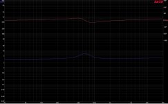
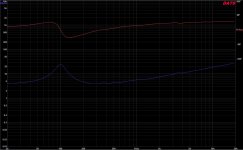
the impedance curve (measured in box with the DATS V2) is more or less ok: the drivers live in their own separate box, and I don't have the situation that you describe.
Below all the 3 curves: any comment is very welcome
tweeter
mids
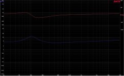
woofers
Let me set up the XO and do what suggested: will be back soon with the results
thanks!
cheers
thanks for the very valuable information!!
jtalden,
Using measurements for the setup process does not require a capacitor to protect the tweeter so long as you are careful to assure that the XOs are active for all measurements.
does it mean that I need one later for the full system, or can I go without? In case I need, what about the Jantzen Audio 82uF 400V (model no.001-0288)?
I'm using the simulator for avoid too many trial and error measurements... (low neighbor/family tolerance 😉 )
Juhazi,
I'm doing all the measurement at 1.5m now, on-axis, 15 and 60 deg off (ground measurements for the woofers). I will use your methodology for check the drivers behaviours
TMM,
the impedance curve (measured in box with the DATS V2) is more or less ok: the drivers live in their own separate box, and I don't have the situation that you describe.
Below all the 3 curves: any comment is very welcome
tweeter

mids

woofers

Let me set up the XO and do what suggested: will be back soon with the results
thanks!
cheers
jtalden,
does it mean that I need one later for the full system, or can I go without? In case I need, what about the Jantzen Audio 82uF 400V (model no.001-0288)?
I'm using the simulator for avoid too many trial and error measurements... (low neighbor/family tolerance 😉 )
I don't use cap on my dome TWs, but I am careful that my DSP XOs are always active when measuring drivers. If you have s need to measure a TW full range for simulation purposes at anything above a very low level or have a concern that that you may make a mistake and somehow disable the XO and thus blow a TW, then it would be a good idea to include one. I will let others suggest the size required as I don't do this.
Dear experts,
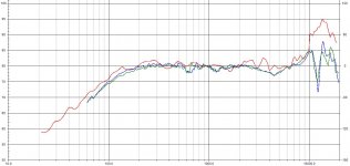
Here my near field measurements, based on the Juhazi instructions
I've compared the in-box with the maker FR (in red), with SPL adjusted, smoothed 1/48
Mids
Woofers
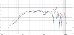
I see some difference in the low frequency for the woofers: is that normal?
What do you think?
thanks for the help!
cheers
Here my near field measurements, based on the Juhazi instructions
I've compared the in-box with the maker FR (in red), with SPL adjusted, smoothed 1/48
Mids

Woofers

I see some difference in the low frequency for the woofers: is that normal?
What do you think?
thanks for the help!
cheers
eriksquires,
thanks for the link, very interesting reading 🙂
Does anyone have any comments about the standing waves and ringing in the box, based on the near field measurements?
Will be really appreciated!
thanks!
cheers
thanks for the link, very interesting reading 🙂
Does anyone have any comments about the standing waves and ringing in the box, based on the near field measurements?
Will be really appreciated!
thanks!
cheers
With regards to the standing waves conducted to the air volume directly from the cone, stuffing works.
AllenB,
the box is filled with Acousta-Stuf Polyfill (1lb per cubic foot of enclosure). I would validate that the design and the stuff inside work, and the cabinet is strong enough, with no ringing or strange behaviour
thanks!
cheers
the box is filled with Acousta-Stuf Polyfill (1lb per cubic foot of enclosure). I would validate that the design and the stuff inside work, and the cabinet is strong enough, with no ringing or strange behaviour
thanks!
cheers
If you're comparing near field measurements to a manufacturer's 2pi far field measurements, there will be differences. At low frequencies the differences are likely due to different back volume size. At high frequencies the differences are due to the different location of the microphone, diffraction, etc. Your measurements look reasonably close to the manufacturer's, so I'd just trust your measurements.
John,
thanks for your answer: this give me confidence in my design 🙂
Will post soon the time delay calculation for review
thanks!
cheers
thanks for your answer: this give me confidence in my design 🙂
Will post soon the time delay calculation for review
thanks!
cheers
- Status
- Not open for further replies.
- Home
- Loudspeakers
- Multi-Way
- Is there a clear way to measure speaker time delay, phase and standing waves?