Hello
Is the length of NFB loop on a pcb are so important ?
From 4706 Gaincard sakura systems web page, "...the length of NFB loop creates a time delay between the original and the return signals and allows noises to enter. To take full advantage of NFB, we shortened the length of the feedback loop on Model 4706 to 9m/m, which includes the length of the resistor. We achieved this breakthrough by utilizing power IC and intricate point-to-point hand wiring."
This Sakura text are for his Gaincard chipamp amplifier, but it should apply to all audio amp.
For myself, I try to keep the NFB loop short on my pcb.
In audio frequencies, the length of NFB loop should not be so critical, but I may be wrong.
Thank
Bye
Gaetan
Last edited:
The bit of reasoning
is certainly specious. The 'time delay' -- presumably signal propagation delay -- is miniscule (1 nanosecond per ~11 inches) compared to the circuitry delays imposed by charging/discharging various capacitances.
And there is absolutely no correlation between delays (regardless of source) and the opportunity for 'noises being allowed to enter'. Utterly specious.
Now, traces on PCB's do travel more slowly than EM waves through free space. If they use Teflon-insulated point-to-point wiring, THAT has slightly faster propagation than other common insulations.
Cheers
.. the length of NFB loop creates a time delay between the original and the return signals and allows noises to enter.
is certainly specious. The 'time delay' -- presumably signal propagation delay -- is miniscule (1 nanosecond per ~11 inches) compared to the circuitry delays imposed by charging/discharging various capacitances.
And there is absolutely no correlation between delays (regardless of source) and the opportunity for 'noises being allowed to enter'. Utterly specious.
Now, traces on PCB's do travel more slowly than EM waves through free space. If they use Teflon-insulated point-to-point wiring, THAT has slightly faster propagation than other common insulations.
Cheers
Last edited:
I got caught out with a chip amp feedback loop length.
It oscillated badly.
I had to make it as short as possible to get rid of oscilllation.
1mm of track is 1nH of inductance.
It doesnt take a massive amount to cause phase delay.
It oscillated badly.
I had to make it as short as possible to get rid of oscilllation.
1mm of track is 1nH of inductance.
It doesnt take a massive amount to cause phase delay.
Nonsense, we are talking audio frequencies, not UHF.the length of NFB loop creates a time delay between the original and the return signals and allows noises to enter.
And in any case, he´s talking "noise", not "stability" , which would be the relevant parameter.
To boot: in a constant current or mixed feedback amplifier the speaker, which IS part of the NFB loop is often or usually METERS away.
Yet no big deal.
Again: METERS, not MILLI-meters away which seem to worry Sakura and Neurochrome so much.
Last edited:
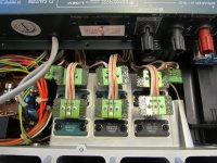
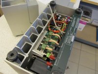
Here's one of three identically wired fastest audio amplifiers(200v/us) with 15 cm of wiring to the final transistors: 60 mhz FT(PNP) and 80 Mhz FT(npn ) final transistors...As someone said...what works for some, never work for others...
Kenwood L-08M on thevintageknob.org
Kenwood L-08M on thevintageknob.org
Attachments
Last edited:
The bit of reasoning
is certainly specious. The 'time delay' -- presumably signal propagation delay -- is miniscule (1 nanosecond per ~11 inches) compared to the circuitry delays imposed by charging/discharging various capacitances.
And there is absolutely no correlation between delays (regardless of source) and the opportunity for 'noises being allowed to enter'. Utterly specious.
Now, traces on PCB's do travel more slowly than EM waves through free space. If they use Teflon-insulated point-to-point wiring, THAT has slightly faster propagation than other common insulations.
Cheers
It’s not the time delay which causes instability. That delay is miniscule. But capacitance from the summing node to ground eats phase margin. If alll those little sub-1-pf capacitances were taken into account in the stability analysis, oscillation can be predicted. Faster propagation = less capacitance per mm so there is some correlation.
Length of the feedback path from output to summing node can contribute To noise and distortion pickup in practical applications. There is mutual inductance between it and any parallel current carrying conductor. It is a great place to pick up power supply hum - it is simply induced. You can get induction distortion from the DC rails, which carry large non-sinusoidal currents. These are just input signals as far as the amp is concerned, so there is no way for the feedback to correct them. Making the feedback physically short just minimizes their opportunities. Other methods will minimize them too, such as running the feedback return alongside (like a twisted pair from both terminals of the output transformer of a tube amp) and keeping current carrying conductors at right angles.
It's not so much the length itself that's a factor, but rather inductance, and that's a function of loop area. That's why e.g. supply +/-/GND need to be kept as closely together as possible, and supply wiring twisted. You need to identify the critical current paths. It won't hurt if you can tighten up the current paths on the input side as well, we are talking inductive coupling after all.
As mentioned, capacitance to ground on the feedback node should be kept to a minimum as well; it can be counteracted by a few pF across feedback if need be.
As mentioned, capacitance to ground on the feedback node should be kept to a minimum as well; it can be counteracted by a few pF across feedback if need be.
Last edited:
- Home
- Amplifiers
- Solid State
- Is the length of NFB loop on a pcb are so important ?