I picked up 25 of them for $1 each a while back too. Apparently triode strapped, they are linear. Now watch the prices go up!
http://www.audiodesignguide.com/New2A3/ETF06TS.pdf
Alternative Pentode Connections. (Page 1)
http://www.audiodesignguide.com/New2A3/ETF06TS.pdf
Alternative Pentode Connections. (Page 1)
Last edited:
Two of the 6888s would make a reasonably good PP amp. Tye g3 to the cathode & treat them like any other high perveance TV pentode. Run the screens at something like 150V for a start.🙂You will need to use some physically small resistors, something like 10 K on the G1 connexion right close to the socket to suppress parasitic oscillation.
The 6888 is a lot like some of the early TV video amplifiers, for example the 6AG7.
I worked on some of that mag core stuff early on but the core drivers were one of the European 9-pin miniature pentodes of that time. They had a top cap for the plate. They were normally used in TV sweep circuits, don't recall the model number tho.
EL81 does look like what we used. There was a lot of research on core memory. But not much out there now.🙂
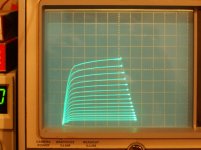
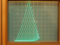
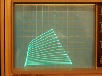
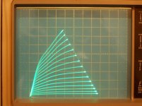
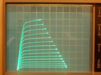
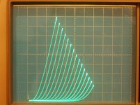
Got the curve tracer fixed today, so I did some curves for the 6888 tube.
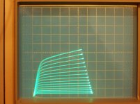
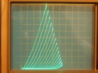
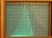
All are at 20mA/div Vert. and 50V/div Horiz.
1) pentode mode, +150V on grid2, +24V on grid3 (to square up knees), -1V steps on grid1
2) pentode mode, +150V on grid2, +8V on grid3 (sorta constant gm on a load line), -1V steps on grid1
3) triode mode, +24V on grid3, -2.5V steps on grid1, grid 2 conn. to plate
4) triode mode, 0V on grid3, -2.5V steps on grid1, grid 2 conn. to plate
5) triode mode, -2.5V steps on grid 1, grid 2 and grid 3 conn. to plate
With +24V on grid 3 in pentode mode, the g2 screen current drops from 12mA to 6mA (over full scan), lowering g2 dissipation by 0.9 Watt (at 150V). Using the 4 to 1 rule for Sweep tubes, every Watt reduced on grid 2 allows 4 more Watts on the plate. So the tube could now be rated at 11.6 Watt plate diss.
These were all run with a 50 Watt load limit resistor in the tracer, 25 Watt average scan. I didn't see any red plating, but the tube sure smelled HOT.
The +8V on grid 3 (2nd pic) is interesting for keeping the curve spacing (gm) near constant over a large range except at the low current end where it would be over-lapped in P-P. Could be quite useful for class AB P-P linearity. Some investigation is in order here I think.
There are some 9 pin tubes with similar characteristics as the 6888, the 6LE8 and 9KC6.
9KC6 has a frame grid, and it hits around 36000 gm when the knees are squared up using +V (+10V to +13V) on grid 3. It appears to be a 12GN7/12HG7 with a dense grid 3 instead of the usual beam plate.
Attachments
Last edited:
Minor correction to the above tube heat figure while on tracer.
A 50 Watt load R limiter would be averaging more like 1/3 that, or 16 Watts over a full scan, rather than the 25 Watt figure I gave above, when I mentioned the tube smelling hot.
(crudely integrating X^2 over 0 to 1 along the 45 degree diagonal, giving 1/3 X^3 or just 1/3 )
A similar integral occurring along any orthoganol line to the constant Watt hyperbolas.
But then there would be a factor of more area in the low power areas near the coordinate axis (due to orthogonals spreading out there), and then the sine wave 60Hz plate V would cause the tube to spend more time near the max power hyperbola (at sine wave peaks). Hopefully, roughly cancelling those effects.
A more complex double integral would be needed to get the fully accurate answer, with even more complication from the pentode knees avoiding the vertical axis, or the triode curves even more, and the extent of grid 1 stepping altering the approach to the 0 current axis. Not worth the effort, would vary for every curve trace setup. Then there is the offset adjustment on the stepping V too.
No, no, not going there......, approx. answer is 1/3 of limiter Watts. My nose says the hot tube was doing 16 Watts (but up-rated for 12 Watts and originally rated for 8 Watts)
Last edited:
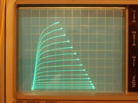
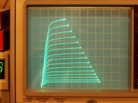
Here is a curve set for the 6888 with 0V on grid3. Then some curves for 9KC6 which is similar except high gm with a frame grid 1.
All are 10 mA/div Vert. and 50V/div Horiz.
1) 6888 with 0V on grid 3, -1.1V steps on grid 1, 150V on grid 2
2) 9KC6 with 0V on grid 3, -0.15V steps on grid 1, 150V on grid 2
3) 9KC6 with +24V on grid 3, -0.15V steps on grid 1, 150V on grid 2
4) 9KC6 in triode mode, 0V on grid 3, -0.4V steps on grid 1, grid 2 conn. to plate
5) 9KC6 pentode again, with +12V on grid 3, 0.17V steps on grid 1, 150V on grid 2
6) curve set 3) fixed
Around +12V on grid 3 for the 9KC6 in pentode gave something like the constant gm case with the 6888, but not as good.
These were all run with a 10 Watt load limiting resistor.
Oops. I just noticed that the grid 1 offset was not set at zero for the 3rd curve set. Top of curves should be about 1.25 div higher for 0 V at grid 1.
Fixed curve set 3) offset in 6)
Attachments
-
 9KC6_10mA_50V_p15Vstps_150Vg2_0Vg3.jpg658.6 KB · Views: 75
 -
 6888_10mA_50V_1p1Vstps_150Vg2_0Vg3.jpg660.5 KB · Views: 79
 -
 9KC6_10mA_50V_p15Vstp_150Vg2_24Vg3.jpg632.3 KB · Views: 79
 -
 9KC6_T_10mA_50V_0p4Vstps_0Vg3.jpg680.9 KB · Views: 81
 -
 9KC6_12Vg3_10mA_50V_0p17Vstp.jpg626.9 KB · Views: 76
 -
 9KC6_10mA_50V__24Vg3_0.15Vstps_150Vg2.jpg651.7 KB · Views: 72
Last edited:
I think a few years ago some government warehouse must have been emptied, as there was a glut of them on the market. I might have bought a lifetime supply of these with some of my plague bucks for $1-$2 each. I'd actually like to get some more 🙂 I bought originally to build the AM transmitter published on the antique radio forums website, and then started thinking of other things to do with them. as a triode, it might work as a concertina phase splitter in a situation where you needed plenty of headroom to prevent clipping. 5W per tube just for the heaters is a bit of a downside unless you live somewhere where it's cold most of the year 🙂
Steve Bench liked the triode curves
http://diyaudioprojects.com/mirror/members.aol.com/sbench102/6888tri.gif
http://diyaudioprojects.com/mirror/members.aol.com/sbench102/6888tri.gif
Seems like EL81 was only mentioned to identify a recollection of using a tube for magnetic core drivers.Steve Bench liked the triode curves
http://diyaudioprojects.com/mirror/members.aol.com/sbench102/6888tri.gif
But since this thread is about tube curves, I have asmall bunch of EL81's. I saw they were used in some PP Philips amps running Class B, and didn't think much about them anymore.
I recently saw a Philips EL81 data sheet that had triode-connected data: (g2-a, g3-k)
Va: 250 V
Vg1: -38
Ia: 40 mA
gm: 5.5 mA/V
ra: 1k
mu: 5.5
6.6 W heater power per tube & anode connector don't scare me off.
But I need to go read (again) how to estimate output transformer primary impedance for an oddity with no triode curves (that I know of).
PP EL81 pentodes still doesn't seem that difficult, and PP EL81 as triodes seems more attractive than 6080's (box o'them, too). Better mu and lower heater power.
People often ask 'why?' but just for a project where I have plenty of spares, why not at least contemplate it on a scale of least worseness?
Which seems more foolish?: PP EL81 pentodes or triodes.
Or is it so foolish, the question has never been posed?
Thanks & Happy Holidays
Murray
- Home
- Amplifiers
- Tubes / Valves
- is the 6888 tube worth messing with???