Guido Tent said:
Hi
If you care or the DC component of the spectral part of the jitter, ppm spec is important.
I do however not mind that DC part, as long as the ppm value is within the redbook spec
Questions to all contributors
- Do we know what jitter is
- Do we know how to measure it and do we have a preference for the unit of measurement
- Do we know how jitter affects DA conversion and what jitter properties of a clock count
It seems many of us are ivolved in the dicussion on a toppic they do not (fully) grasp
Answers to these questions are required to improve the discussion
Guido
I'm surprised You do not know the answer to these questions as You supply clocks as I understand it, or are You just challenging the forum ;-)
I'll give it a try:
yes *we* do:
Jitter is deviation in time from the nominal sampling frequency (this case) in a PCM sysem. It's somethimes (theleopny digital links) measured in ui which correleates to part of the clock frequency (time actually) but is of cource also translatable to time (s). Jitter is defined as timing deviation < 10 ui and when exceeded defined as wander. (Btw, wander would make the CD player play out of tune - this now starts to get into ppm territory)
Do we know how to measure it and do we have a preference for the unit of measurement:
Spectral analysis where errors show up as a level (db) of spectral components other than the clock freq. How level is transposed to time is beoynd me :-(
Miller Audio Research sems to make a sutiable unit fo jitter measurement.
and finally ...
- Do we know how jitter affects DA conversion and what jitter properties of a clock count
- It sounds **** + that all count which are present in the audio range :-D
btw: there are only 2 jitter properties, freq and level!
/j
TNT said:
I'm surprised You do not know the answer to these questions as You supply clocks as I understand it, or are You just challenging the forum ;-)
I'll give it a try:
yes *we* do:
Jitter is deviation in time from the nominal sampling frequency (this case) in a PCM sysem. It's somethimes (theleopny digital links) measured in ui which correleates to part of the clock frequency (time actually) but is of cource also translatable to time (s). Jitter is defined as timing deviation < 10 ui and when exceeded defined as wander. (Btw, wander would make the CD player play out of tune - this now starts to get into ppm territory)
Do we know how to measure it and do we have a preference for the unit of measurement:
Spectral analysis where errors show up as a level (db) of spectral components other than the clock freq. How level is transposed to time is beoynd me :-(
Miller Audio Research sems to make a sutiable unit fo jitter measurement.
and finally ...
- Do we know how jitter affects DA conversion and what jitter properties of a clock count
- It sounds **** + that all count which are present in the audio range :-D
btw: there are only 2 jitter properties, freq and level!
/j
Hi,
I did not state that I myself cannot answer te questions. To improve the discussion, it may help to put the noses in the same direction. From that point of view, I challenge the forum.
Jitter is the difference in time of the actual and expected (i.e. perfect) timing moment (in the case of a clock the slope, positive or negative). The range of interest may be cycle to cycle, or cycle to 100k cycle, for example.
The timing error will lead to amplitude errors at the moment of conversion. This is why we "hear" jitter. The sensitivity of ADC's or DAC's differ due to concept and implementation.
Could you provide me with a link of the Miller equipment ?
best regards,
Guido Tent said:
Could you provide me with a link of the Miller equipment ?
best regards,
Google strikes again...
www.milleraudioresearch.com
Not very exciting. Another tiresome product which obtains jitter numbers from measurements made on the derived audio after a D/A process. This is by far the easier measurement problem (and hence much cheaper). I've never been fond of these derived type measurement.
Measurement of jitter directly on the higher speed clock or SPDIF etc. signals is much more difficult and costly. But it is the only one which you can guarantee to be truly accurate.
James
nemestra said:
Google strikes again...
www.milleraudioresearch.com
Not very exciting. Another tiresome product which obtains jitter numbers from measurements made on the derived audio after a D/A process. This is by far the easier measurement problem (and hence much cheaper). I've never been fond of these derived type measurement.
Measurement of jitter directly on the higher speed clock or SPDIF etc. signals is much more difficult and costly. But it is the only one which you can guarantee to be truly accurate.
James
James,
Thanks for feedback. Ofcourse I googled, found that site, but could no find the jitter measurement equipment, which is confirmed by your mail, thanks.
Measuring on SPDIF indeed is only part of the story, finally the conversion clock quality and all the noise entering DAC chips is what counts.....
cheers
nemestra said:
Google strikes again...
www.milleraudioresearch.com
Not very exciting. Another tiresome product which obtains jitter numbers from measurements made on the derived audio after a D/A process. This is by far the easier measurement problem (and hence much cheaper). I've never been fond of these derived type measurement.
Measurement of jitter directly on the higher speed clock or SPDIF etc. signals is much more difficult and costly. But it is the only one which you can guarantee to be truly accurate.
James
Well I think that the only really interesting aspect is what You get on the output. I mean - the D/A chip could do a lot of magic stuff- or not .....
/
PS. Guido - I know You know this stuff - I was just a bit challening back 🙂 DS
/
TNT said:
Well I think that the only really interesting aspect is what You get on the output. I mean - the D/A chip could do a lot of magic stuff- or not .....
/
PS. Guido - I know You know this stuff - I was just a bit challening back 🙂 DS
/
Hi TNT
From perception point of view, yes, what you get at the output is what counts, allthough I still cannot measure all the things that I hear......
In addition, recalculating jitter from analog output properties requires lot of insight info on the cip under test, which is why the Stereophile jitter figures are useless.
The discussion however was about jitter, as such, not strictly what it causes.
cheers
OK!
Do You feel that you can correlate jitter meas in the digital domain with the audible result?
/
Do You feel that you can correlate jitter meas in the digital domain with the audible result?
/
Guido Tent said:
I did not state that I myself cannot answer te questions. To improve the discussion, it may help to put the noses in the same direction. From that point of view, I challenge the forum.
Jitter is the condition of mankind wherein the noses point in the same directiion but at slightly different moment in time.
...too many years of philosophy...
jackinnj said:
Jitter is the condition of mankind wherein the noses point in the same directiion but at slightly different moment in time.
...too many years of philosophy...
I'd like to nominate this definition !
thanks
pb said:Hi everybody,
I though I share some of my thoughts:
Ovenizing the oscillator helps with the long term frequency stability (drift) not the jitter (short term stability).
http://www.odyseus.nildram.co.uk/Systems_And_Devices_Files/PhaseNoise.pdf
Hi,pb
I had discussed the jitter of XO with my firends in a Chinese forum.
http://www.hifidiy.net/dispbbs.asp?boardID=2&ID=4435&skin=0
Although I got less infos of jitter before,I follow you (and Mr. Guido Tent)😉 after I read some books and articles....
cheers
X.G.
X.G.
Good luck with your project!
A nice paper form Agilent for all those interested in mathematical relation between phase noise and jitter:
http://eesof.tm.agilent.com/pdf/jitter_phasenoise.pdf
I did search the previous threads, it was fun to read but results were quite inconclusive.
I liked the esoteric stuff though. (military spec ECL gates etc)
I might add that the lowest phase noise I have seen in paper was a cryogenic sapphire dielectric oscillator.
Where do I order liquid nitrogen? 😉
Of course what I really would like is a summary but you can't really expect it from the forum e-mails
- the reader is supposed to make up his own mind.
Pity that the DIYAudio Wiki is all but devoid of anything except titles but I think we can only blame ourselves for it .
The subject is really interesting - it would be interesting to have an audio related go at it.
Cheers,
Przemek
PS A book excerpt hinting on nonlinearities influencing the 1/f noise close to the carrier (audio related?): page 4
http://www.icsl.ucla.edu/aagroup/PDF_files/kluwer.pdf
hi,Przemek
what you say(that the noise colse to the carrier is much related to the audio)maybe darn right 😉
a Chinese book about low noise circuit,which I read serveral months ago, say that the 1/f noise of OSC transistor is important for phase noise as well.
another Chinese handbook which I re-read serveral weeks ago,show the details of OCXO and TCXO circuit.Although the frequency stability of this OCXO is much better than TCXO(OCXO is +/- 0.01PPM @per week ,TCXO is 5PPM),I found nothing(for 'reduce jitter' ) except for stable the temperature/temperature compersation
cheers,
X.G.
thanks for your link.....but...I am a bit afraid of the mathematics of electronic😉,I just like DIY audio,and/so want to know how should we do😀 😉pb said:X.G.
Good luck with your project!
A nice paper form Agilent for all those interested in mathematical relation between phase noise and jitter:
http://eesof.tm.agilent.com/pdf/jitter_phasenoise.pdf
pb said:A book excerpt hinting on nonlinearities influencing the 1/f noise close to the carrier (audio related?): page 4
http://www.icsl.ucla.edu/aagroup/PDF_files/kluwer.pdf
what you say(that the noise colse to the carrier is much related to the audio)maybe darn right 😉
a Chinese book about low noise circuit,which I read serveral months ago, say that the 1/f noise of OSC transistor is important for phase noise as well.
another Chinese handbook which I re-read serveral weeks ago,show the details of OCXO and TCXO circuit.Although the frequency stability of this OCXO is much better than TCXO(OCXO is +/- 0.01PPM @per week
,TCXO is 5PPM),I found nothing(for 'reduce jitter' ) except for stable the temperature/temperature compersation cheers,
X.G.
Long post...
I wrote this a long time ago when I was asking similar questions to the ones in this thread, so perhaps it will be helpful to someone...
By Shannon's information theory, an Analogue to Digital Convertor (ADC) converts information from the voltage domain to the time domain, whereas a Digital to Analogue Convertor (DAC) does the inverse. In the final analysis, all DACs drive charge into a capacitor. This process may be clearly visible, as in a 1-bit DAC followed by a single capacitor filter, but it may be concealed, such as in a multibit DAC followed by a complex LC reconstruction filter.
The voltage across a capacitor is proportional to its charge, and if charging current is constant, then capacitor voltage will be proportional to charging time. The DAC capacitor charges for the period of the sample clock, so if sample clock time changes, capacitor voltage will change proportionately. Thus clock jitter is converted into amplitude distortion in accordance with Shannon, and the requirement for a low jitter sample clock has been established.
Requirements for sustained oscillation:
To produce sustained oscillations (whether mechanical, or electrical) we need the following:
(1). Frequency selective mechanism: This could be a combination of an inductor and a capacitor, or the balance wheel and spring in a "clockwork" clock, or a transducer with a mechanical resonance such as a quartz crystal.
(2). Energy input: The frequency selective mechanism always has losses, and must receive energy to compensate for these losses and maintain oscillation.
The balance between energy input and losses is crucial. If less energy is received than is lost, then oscillation amplitude will gradually decay until it stops. If too much energy is received, oscillation amplitude will build up without limit. In the practical world, infinite oscillation amplitude is not possible, and will be limited by power supply rails in an electrical circuit, or by mechanical stops in a clock.
Mechanical considerations:
The master clock in a digital system is invariably a quartz crystal, which is a mechanical resonator combined with a transducer.
The simplest mechanical resonance relies on Hooke's Law providing a restoring force to the mass suspended by the spring, and resonant frequency is determined by:
f=1 / [2 pi sqrt (mC)]
Where:
m = suspended mass
C = compliance of spring
It can be seen that resonant frequency is determined by spring compliance, but practical springs do not behave with the linearity implied by Hooke's Law, and have compliance that changes with amplitude, implying variable resonant frequency. A quartz crystal is a more complex resonator, but it still suffers from the preceding limitations.
Although crystal losses are very low, they are not zero, so additional energy must be supplied from an external source to compensate for these losses and maintain oscillation. The amount of additional energy supplied each cycle determines oscillation amplitude, and an ideal control circuit would maintain constant oscillation amplitude at all times. However, if oscillation amplitude gently changes with time, then the peak deflection of the crystal spring will change, and resonant frequency will change. Considered in the time axis, this is jitter...
In order to optimise the mechanical oscillation of the crystal, and thereby minimise jitter, the physical oscillation amplitude of the crystal should be constant.
Distortion is a second order effect arising from spring non-linearity. For any spring, the smaller the deflection, the better the approximation to Hooke's Law. Therefore, to minimise distortion arising from imperfect amplitude stabilisation, the voltage across the crystal should be low.
Crystals may have spurious responses at -20dB a few 100kHz away from their main resonance. Better crystals minimize these spuriae, alternatively, a ½ section lattice filter can be used (looks like a transformer feeding a centre tapped rectifier, but uses crystals instead of diodes).
Electronic considerations:
Although oscillators may produce either sine or square waves, any oscillator may be considered to be a sinusoidal oscillator enclosed by an amplitude stabilisation circuit of variable efficacy. Methods of amplitude stabilisation are:
Supply rail limiting (CMOS invertor): Very crude, far too much stress applied to crystal.
VBE or diode limiting (single transistor RF oscillator): Can be good, but relies on high Q of crystal.
Variable gain amplifier plus side chain: Rarely seen, has the potential to be the best, but is complex.
Thermistor ( AF Wien bridge): Not practical at RF
The simplest (and arguably the best) method of amplitude stabilisation is the thermistor. In combination with a Wien bridge, this produces low distortion sine waves, despite the fact that the Q of the Wien bridge is low (Q = 3). Viewing this in reverse, any method of producing low distortion sine waves (that does not rely on filtering) must imply a good amplitude stabilisation system and therefore low jitter. Looking at the opposite extreme, it is alarming to find that the most common master clock in many domestic CD players is based on the (cheap) CMOS invertor. This oscillator has extremely crude amplitude stabilisation, and applies high voltages to the crystal, but works because Q for a crystal is high (Q is typically 18,000). It is no wonder that almost any modification improves this circuit!
The ideal master clock for a digital system would combine the high Q of the crystal with a good amplitude stabilisation system to produce a sine wave. The crystal would operate in series mode and be driven from a low impedance source in order to maximise its Q, and there would be a low voltage across the crystal to minimise deflection non-linearities within the crystal. The low distortion/jitter sinusoidal crystal oscillator would be followed by a buffer to isolate it from the comparator needed to provide the square wave clock required by the digital circuitry.
Comparator problems:
A comparator may be considered to be a 1-bit ADC, and as such, it will convert amplitude variations into time variations. In order to switch the comparator as sharply as possible and minimise this problem, it is conventional to sample the sine wave at the zero crossing point where dV/dt is at a maximum. Even so, if the amplitude of the sine wave changes, then dV/dt at the zero crossing will also change, and because practical comparators require a finite input voltage to change the output state, this will change the time at which the comparator switches.
Poor amplitude stabilisation of the sine wave oscillator not only causes jitter within the oscillator, but also at the conversion from a sine wave to a square wave.
Dedicated comparators draw high input current transients as they switch, because one transistor is being switched off and another is switched on, so the oscillator must be buffered from the comparator, and the buffer must be capable of sourcing these pulses without disturbing the crystal oscillator.
A variable gain amplifier plus side chain would be a four-quadrant multiplier (the output is x times y, so if y is DC it's a variable gain amplifier) plus a rectifier, smoothing to give DC, plus comparison to DC reference and finally, DC fed to the variable gain amplifier. It all tends to get quite complex. I've (hopefully) attached the diagram of an untested circuit.
Attachments
Hi,
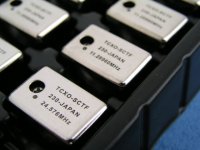
sorry I had not enough knowledge to versify that the TCXO had lower jitter or not. Factory only told me that this was accurancy sharp cut cystal & very stable within 2 ppm. Pls see the 11.2896 & 24.5760 TCXO within <2ppm. All was stainess enclose with gold plated legs.
Pls see the two photos & one will be the test result follow with the TCXO.
thx
thomas
Attachments

tube-lover said:Hi dear all,
more photos about the test result.
any comment for that.
thx
thomas
Hi
ppm values are NOT relevant for the jitter discussion
regards
- Status
- Not open for further replies.
- Home
- Source & Line
- Digital Source
- Is TCXO really good for re-clock??