When I found PSU simulator from Duncan's, I shouted with joy!
But I see some weird things happen now. See the picture attached please.
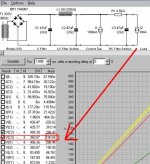
I set 100ma for output tube stage, and 6ma for driver tube from 330V (RMS) transformer. I added 4k5 in order to drop voltage for driver stage. Oh, I am talking about a pentode SE amp.
Well, according to my manual calculation, voltage in c2 should be around 250V, because 27V drops from the previous one by 6maX4.5k)
But the result says 190V. Wow, I cannot understand this result. Moreover, when I measured a REAL amp with my tester, I found that my calculation was right and PSU II was wrong.
I tried to contact Duncan for this matter, no reply has been made. Anybody can explain this? What did I miss?
But I see some weird things happen now. See the picture attached please.
I set 100ma for output tube stage, and 6ma for driver tube from 330V (RMS) transformer. I added 4k5 in order to drop voltage for driver stage. Oh, I am talking about a pentode SE amp.
Well, according to my manual calculation, voltage in c2 should be around 250V, because 27V drops from the previous one by 6maX4.5k)
But the result says 190V. Wow, I cannot understand this result. Moreover, when I measured a REAL amp with my tester, I found that my calculation was right and PSU II was wrong.
I tried to contact Duncan for this matter, no reply has been made. Anybody can explain this? What did I miss?
Attachments
Buddy Hackett: Ask me what's the secret to comedy.
Johnny Carson: OK, I'll bite. What's the secret to----
Buddy Hackett: --TIMING!!!!
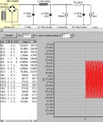
Try setting the sim to 1 second after a 10 second delay. Then think about RC time constants.
Johnny Carson: OK, I'll bite. What's the secret to----
Buddy Hackett: --TIMING!!!!
Try setting the sim to 1 second after a 10 second delay. Then think about RC time constants.

I get 213 V across C3, after a 10 second delay.
(edit...) Hang on, that voltage reading has m after it, so does that mean millivolt? Or maybe that is just the ripple voltage ? Now I'm confused...
(edit...) Hang on, that voltage reading has m after it, so does that mean millivolt? Or maybe that is just the ripple voltage ? Now I'm confused...
I doubt that it's the simulator - it's probably that your model doesn't match reality.
Is the no-load voltage and resistance for the transformer correct? It has to include not just the secondary R but the reflected primary R as well.
Is the ESR of the caps and inductors the same as your actual parts?
Beware using current sources in simulations - they are not real. For example, what's the voltage that appears across an unconnected current source? Inifinite. You're safer using a resistor with the equivalent load.
So if you already have the circuit built and measured, why are you worried about the simulation?
🙂
Pete
- Status
- Not open for further replies.
- Home
- Amplifiers
- Tubes / Valves
- Is PSU Designer II correct?