Hi, quite new here so not sure where to post. Mods, feel free to move this 🙂
I've designed (if you can call ripping off two things from other people and sticking them together "designing") a guitar effects pedal for a university project. The circuit is very simple - just a buffer and a high-pass filter. I built the thing, but it's not working! 🙁 When I engage the pedal, I get no sound. At all.
I know how to do true bypass switching so I've left that out of the schematic. I'm quite new to electronics, but I read a lot, haha. I've tried to write out the schematic as literally as possible. I forgot to write the op-amp power supply connections - these literally connect straight to the battery, right? Or do I need to add additional stuff there to make it work?
The buffer is from muzique.com, the filter circuit itself I forget where I got it - probably Art of Electronics. It's a standard Sallen-Key in any case. The op-amp is a 4558 (had a bunch lying around).
Could you geniuses please have a look at my schematic and inform me if there's something wrong with it? I know troubleshooting is a difficult process, so I want to know where to look - if I know my schematic is perfect then obviously the problem lies in construction. Sorry about the lame picture, I literally photographed it from my notebook!
Thanks so much guys! Quick replies would be highly appreciated as I have to hand this in on Thursday. 😀
Attachments
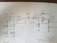
You don't use 470uF and 1K resistors in a filter circuit, the capacitors are FAR too big and the resistors much too small.
You also don't appear to be biasing the second opamp, and the first one biased via a 1M is probably too high for a 4558?.
You also don't appear to be biasing the second opamp, and the first one biased via a 1M is probably too high for a 4558?.
There are a Lot of problems with this curcuit , The first stage seems okay but the Opamp should be a Fet input opamp because of the 1m input impedance .... the output of the First stage has a 10uf and a 470uF in series , get rid of the 10uF as it isn"t needed .......
The Values of the second stage filter don"t seem right but I haven"t taken the time to calculate .....
the second Stage isn"t biased so it won"t work , the way you have it , it would work with a Dual PSU but not with a single supply , you need to Bias the input to 1/2 supply like the first stage , the second stage will also need an ouput cap with a single supply ......
Cheers
Thanks so much for your help, both of you. 🙂 I'm still learning! DIY audio is awesome. (The concept and the forum, haha.)
I should point out the two caps on the right-hand side of the schematic are both 470 *nano*, not micro.
I should point out the two caps on the right-hand side of the schematic are both 470 *nano*, not micro.
- Status
- Not open for further replies.