Is it worth measuring TS parameters for sub drivers?
It seems not too difficult to measure fs, VAS, Qts and a few other parameters, but is it worthwhile/necessary?
I'm working on a vented sub design that will use a rectangular vent which will have large flares and will be tapered, hence I will also need to make a prototype to know what tuning will be achieved. It won't be a simple radius, but rather a more complex tapered profile with a flare at the end.
Normally I wouldn't be concerned, but this box will be elaborate enough to be a bit more fussy about "getting it right!"
I've never measured one of my subs....
BUT if I had decent measuring equipment and ample time(well I do have the time) then I would go for measuring my woofers
BUT if I had decent measuring equipment and ample time(well I do have the time) then I would go for measuring my woofers
What kind of radius? Exponential, involute? I guess measuring the T/S parameters would be useful if you had a reasonably accurate set of formulas to predict the response. If you don't have these, then it really is trial and error to get it right and measureing the T/S parameters would get you no closer to a finished box than using the published T/S parameters. Now if you wanted to define a set of equations for the rest of us to use in designing similar systems (you know we would love you for it!) then having accurate parameters would be essential to deriving usable equations. If it's just a design for your own listening pleasure I don't see the need to measure T/S.
-Troy
-Troy
According to Deon Bearden of AE Speakers, it is difficult to measure this type of driver accurately. If doing a delta-mass measurement, you need to be willing to practically glue the mass onto the cone. The mass needs to be big enough to make a substantial shift in Fo, so those 5-gram nickels probably won't work. also, all measurements would need to be made with the driver in the vertical orientation to avoid biasing the suspension.
My driver is the AV12 hence I have TS parameters, my reason for measuring would be to check that my driver is consistent with the published numbers.
I don't intend to make some new equations for vent design. I usually skip over equations in any white paper!
BAM,
I'm curious why it would be difficult to measure ... I'm prepared to take the published specs on mms, as that is not likely to change. However, fs, VAS, Qts look pretty straightforward, I think even perhaps cms IIRC.
If it turns out unnecessary then I have at least learnt something, and I do intend to set up basic measurement capability as well, measuring response and possibly even getting into distortion measurements at some stage.
The vent I have in mind for my two AV12 drivers is approx 90 x 280mm in cross section with probably about a 90mm radius flare on the inside and on the outside something much larger, probably more like a horn profile transitioning into a fairly large radius. The area of the vent mouth would be about 600 x 200. The floor will be used as one of the walls of the vent.
I think I'll have to make a prototype of the vent, otherwise I'll have to guess the tuning and err on the side of letting it be tuned lower than intended. It will have two 90 degree bends.
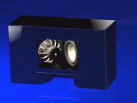
When it's done, I'll publish my results online. I'll show how simulations compared to actual measurements as well as the actual tuning point achieved, which will be interesting to anyone who builds a vent with large flares. I'd also like to do some large signal measurements and show power compresssion, as I think this is something most diyers don't have the luxury of knowing.
A picture tells it best:
I don't intend to make some new equations for vent design. I usually skip over equations in any white paper!
BAM,
I'm curious why it would be difficult to measure ... I'm prepared to take the published specs on mms, as that is not likely to change. However, fs, VAS, Qts look pretty straightforward, I think even perhaps cms IIRC.
If it turns out unnecessary then I have at least learnt something, and I do intend to set up basic measurement capability as well, measuring response and possibly even getting into distortion measurements at some stage.
The vent I have in mind for my two AV12 drivers is approx 90 x 280mm in cross section with probably about a 90mm radius flare on the inside and on the outside something much larger, probably more like a horn profile transitioning into a fairly large radius. The area of the vent mouth would be about 600 x 200. The floor will be used as one of the walls of the vent.
I think I'll have to make a prototype of the vent, otherwise I'll have to guess the tuning and err on the side of letting it be tuned lower than intended. It will have two 90 degree bends.
When it's done, I'll publish my results online. I'll show how simulations compared to actual measurements as well as the actual tuning point achieved, which will be interesting to anyone who builds a vent with large flares. I'd also like to do some large signal measurements and show power compresssion, as I think this is something most diyers don't have the luxury of knowing.
A picture tells it best:
Attachments
T/S parameters Are important in designing enclosures for our speakers! But for subs, if you buy a respectable brand, you're probably getting pretty accurate specs from the manufacture, perhaps even more accurate than what you can measure at home.
Now advertised Frequency response spl charts are useless mostly
Here's the thing, the T/S parameters will have nothing to do with how you should taper your port to get the best aerodynamics. They do help choose what frequency you should tune to and what enclosure volume you should use.
Now advertised Frequency response spl charts are useless mostly
Here's the thing, the T/S parameters will have nothing to do with how you should taper your port to get the best aerodynamics. They do help choose what frequency you should tune to and what enclosure volume you should use.
I'll second Awdy's response regarding accuracy of specs, and especially if its coming from a smaller manufacturer such as AE (no disrespect intended to John). Having worked in an environment where drivers were being pumped at 1000+ pcs/day, parameters tended to sway a fair bit but still had to fall within reasonable limits for the intended desgn.
I would trust a small manufacturer with posted specs more than I would trust a conglomerate who cranked 'em out till there's no tomorrow... UNLESS they actually state the allowed tolerances publicly.
Mark
I would trust a small manufacturer with posted specs more than I would trust a conglomerate who cranked 'em out till there's no tomorrow... UNLESS they actually state the allowed tolerances publicly.
Mark
I'm going ahead with measuring anyway, not so much as it's really necessary, but more because I'm curious and want to be able to do it!
The problem I'm having now is getting a constant voltage. I need to be able to test that the voltage from the amplifier is constant with a sweep, so that I can find out the fs! Ideas anyone?
The problem I'm having now is getting a constant voltage. I need to be able to test that the voltage from the amplifier is constant with a sweep, so that I can find out the fs! Ideas anyone?
Hi,
the voltage does not need to be constant.
You measure the voltage across the series feed resistor and the voltage across the speaker( if you use the voltage method). The peak across the speaker identifies the Fs and then you work on RATIO of voltages to identify the frequencies either side of Fs.
This needs accurate frequency measurement for bass units when the Lower F may be only 12 to 15Hz. You will need three significant figures (preferably four) to minimise errors in the calculated Qs. This is where I struggled (I used an oscillator rather than a computer generated signal) but my numbers agreed reasonably with the manufacturer.
It did identify differences between units and this allowed me to tune the Q when fitted into the vented cabinet. Bass on the higher Q drive unit improved a lot when a small series resistor was added to make the final Q match the other drive unit. Yes, I designed the cabinets to match the lower Q drive unit.
Hi,
yes permanently and no to power handling. The resistor was a small value to make a fine adjustment to the speaker Q. I cannot recall the value but I used a short length of resistance wire inserted into one side of the speaker cable. It may have been 0r1 to 0r3, that sort of order spread over about 120mm of cable length. So heat is not a problem nor is power reduction. Hi Fidelity is more important.
It is only fitted to the bass cable since I have only run bi-wired or bi-amplified for very many years. The treble and mid units were not corrected.
- Status
- Not open for further replies.
- Home
- Loudspeakers
- Subwoofers
- Is it worth measuring TS parameters for sub drivers?