Hi guys, I've this pair of old crossover boards from a three ways vintage speakers (I don't have them anymore).
I can remember they were 8 ohm, three ways, 70 watt max, 8" woofer, simple cone mid-range and a simple dome tweeter.
The thing that interests me the most is the woofer frequency cut-off.
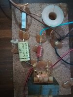
I add a picture of this crossover with the few informations about the resistors and capacitor I can read:
The yellow ITT capacitor is 4,7 uF.
On the white resistor I can read Farem (an italian brand I suppose) 5/A, 3 R 9, 10%.
On the brown smaller resistor I read M(an unknown letter)T-2, 33, 5%.
The small transformer, I presume, was connected to the woofer.
Please could you help me please🙂?
Thank you very much in advance.
Best Regards.
I can remember they were 8 ohm, three ways, 70 watt max, 8" woofer, simple cone mid-range and a simple dome tweeter.
The thing that interests me the most is the woofer frequency cut-off.
I add a picture of this crossover with the few informations about the resistors and capacitor I can read:
The yellow ITT capacitor is 4,7 uF.
On the white resistor I can read Farem (an italian brand I suppose) 5/A, 3 R 9, 10%.
On the brown smaller resistor I read M(an unknown letter)T-2, 33, 5%.
The small transformer, I presume, was connected to the woofer.
Please could you help me please🙂?
Thank you very much in advance.
Best Regards.
Attachments
Normally I might ask you to trace the woofer circuit. However there will be some uncertainty due to not knowing the coil values, and some due to not knowing the driver responses.
Thank you Allen!
does exist some way to calculate the coil values?😕
Sorry for the stupid question.
Regards.
does exist some way to calculate the coil values?😕
Sorry for the stupid question.
Regards.
You can measure them, I think that would be the most reasonable way. If you go that way there are a few things you might do depending on the equipment you have.
You can use XSim to simulate your entire circuit, including speakers, and see what yo come up with. However you'll need the part values. For the coils you can use DATS (Dayton Audio) or a jig and Room EQ Wizard.
Once you have that, draw your schematic in XSim and look at the output.
Once you have that, draw your schematic in XSim and look at the output.
You can measure them, I think that would be the most reasonable way. If you go that way there are a few things you might do depending on the equipment you have.
Hi Allen, thank you for your reply.
I'm so ashamed to ask you the following question, but I' m still a newbie: o
I've a multimeter, could it help, somehow, to calculate the coil value?
Please forgive my ignorance!🙁
Thank you very much!Regards!
Yes you can use your multimeter if you can send tones thru the crossover. I will take some time and effort, tho. Allen will explain further.
Yes, I'd be delighted. 🙂
One idea I had was to take the crossover, place 8 ohm resistors in where the drivers went, feed it with a signal sweep and measure the response. This kind of operation can be done these days with just a computer and the right software. This way you don't actually need to know the value of the coil. The result is a rough idea of the full response.
If any of these procedures appeals to you we can go deeper into them.
If you have a multimeter that measures inductance then simply make sure that one leg of the inductor is free of being connected to the circuit, and measure while away from metal objects.
Another way is to connect the coil, together with a known capacitor, against a resistance. Then sweep all frequencies and measure for the resonance frequency. You use a simple formula to extract the value. This can also be done these days using only a computer.
Thank you guys for your great support.
I repeat, sorry for my ignorance!🙁
I saw this cheap inductance tester...can it work for my purpose?:
Lc100a Digitale Lcd Ad Alta Precisione Di Capacita Di Induttanza Lc Meter Condensatore Tester 1pf-100mf 1uh-100h Lc100 A Con Clip Di Prova - Buy Lc100a Digital Lcd With Testing Clip,1pf-100mf 1uh-100h Lc100 A,High Precision Inductance Capacitance Lc Meter Capacitor Tester Product on Alibaba.com
I'm a newbie, but I'd like to learn!
Thank you in advance for your patience and kindness!🙂
Best Regards
Thank you, Allen!!!😱
Last newbie question: could I measure the capacitors value?😕
Thank you again!
Regards!
Last newbie question: could I measure the capacitors value?😕
Thank you again!
Regards!

- Home
- Loudspeakers
- Multi-Way
- is it possible to get frequency values from this old crossover?