Hello I started to increase (to 640 ohm) the cathode resistor of my single ended mounting rolling KT66/EL34/6L6 in order to move from hot to cold bias (30-40ma) per tube.
I've never seen a cathode resistor higher than 620 ohm….
I like the sonic result, much more clean and open in the mid and less fatiguing.
I have measured higher THD%, mainly second harmonic, but in the meantime a great reduction of the Third and odd harmonics: in effect with cold bias we have asymmetrical clipping starting on the bottom end of the wave.
So why everybody pushes to have hot bias, more odd harmonics, less tube life, more saturating DC current in the OT, higher sag and reduction in the power supply voltage due to the higher current??
Is this the fair price for just few milliwatt of extra output power (at great THD% levels in any case)?
Last edited:
With some music (Heavy Metal?) slightly more odd harmonics might be preferable.
Also, some tubes actually generate less odd harmonic content at higher bias. I have seen this with the 6P41S.
And it may depend on whether you are running UL, Triode, or Pentode/Tetrode mode.
Also, some tubes actually generate less odd harmonic content at higher bias. I have seen this with the 6P41S.
And it may depend on whether you are running UL, Triode, or Pentode/Tetrode mode.
It would be more interesting to discuss, if you'd provide more info on the circuit and operating conditions, maybe loadlines.
Is this triode mode or pentode/tetrode?
Is this triode mode or pentode/tetrode?
It would be more interesting to discuss, if you'd provide more info on the circuit and operating conditions, maybe loadlines.
Is this triode mode or pentode/tetrode?
Testing in triode mode, 310 Volt Power supply, single ended
Which tube? All three?
Does your amp have global feedback? I doubt it if you seriously have audible difference when changing operating point.
Maybe the change in operating conditions has increased the plate resistance, if your speakers have a bump in the midrange then the increased output Z might be causing your perceived increase in mid range. IF the lower end is tighter then as you have mentioned the decrease in current through the primary might relax the core from getting saturated.
Distortion analysis only tells us part of the picture.
Preferably with instrument tuned in a harsh A 440Hz or worse 444HZ.With some music (Heavy Metal?) slightly more odd harmonics might be preferable.
Also, some tubes actually generate less odd harmonic content at higher bias. I have seen this with the 6P41S.
And it may depend on whether you are running UL, Triode, or Pentode/Tetrode mode.
This way heavy metal will have all the stridency it deserves.
Hello I started to increase (to 640 ohm) the cathode resistor of my single ended mounting rolling KT66/EL34/6L6 in order to move from hot to cold bias (30-40ma) per tube.
So why everybody pushes to have hot bias, more odd harmonics, less tube life, more saturating DC current in the OT, higher sag and reduction in the power supply voltage due to the higher current??
Is this the fair price for just few milliwatt of extra output power (at great THD% levels in any case)?
Single ended must work in Class A. The hotter the Q-point bias, the more output swing and power.
For PP Class AB, hotter Q-point bias means less x-over, as you're delaying the plate current cutoff. It also might put the Q-point in a more linear portion of the plate characteristic to reduce h3 and higher harmonics. That's how it was with PP 6BQ6GA's. 25mA/plate kept the finals within the published PD= 11W spec, but 50mA/plate showed less distortion both on the loadline, and in practice even though this busts the spec.
The 6BQ6GA is a TV HD final, and the specs are very conservative, considering the intended use and it can stand more PD in the much less demanding service as an audio final. Hotter bias makes for better sonics, at least in this case.
The spec sheet makes no mention of use as an audio final, but the 6BQ6GA offers sonic excellence in that service. Other HDs do too.
One thing to be careful of when testing harmonics vs bias condition is the interaction with the driver tube and possible partial harmonic cancellation.
I have seen cases where changing the bias of the output tube results in changes in the harmonic spectrum as the result of this. Change the driver tube to a different type tube, and watch the spectrum take on a totally different set of harmonics as you sweep the bias.
I have seen cases where changing the bias of the output tube results in changes in the harmonic spectrum as the result of this. Change the driver tube to a different type tube, and watch the spectrum take on a totally different set of harmonics as you sweep the bias.
One of the beauties of having regulated AC feeding my 833C amps and adjustable regulated bias is the ability to try different input voltages easily. I've recently dropped the input AC voltage to 110V from 117V, and then adjusted the cathode bias voltage down to maintain the same 160mA plate current through the 833C. The sound becomes a little more relaxed and a bit smoother, and the transformers and chokes, while not loud before, have become pretty much silent. The slight, normal buzzing I can hear with my ear to the speaker drivers has also lessened. The heat sink on the cathode bias voltage regulator mosfet is a couple degrees cooler, too. So far I'm liking the lower voltage - it does drop my plate voltage from 2.3kV to 2.1kV and my theoretical output power from 200 to 180 Watts, but I never use all that power anyway.
Just thought I'd share.
Just thought I'd share.
The spec sheet makes no mention of use as an audio final, but the 6BQ6GA offers sonic excellence in that service. Other HDs do too.
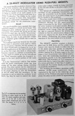
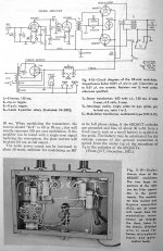
One of the 1960's ARRL handbooks shows the 6BQ6 in PP as a 20-25W modulator (audio amp).A nice feature is using a VR150 between G2 and K as the G2 Vreg so the G2 voltage is not affected by the varying cathode current. The circuit is very conservative on the tube.
The tube has been discussed in detail here:
http://www.diyaudio.com/forums/blogs/miles-prower/953-featured-vt-6bq6.html
and
http://www.diyaudio.com/forums/tubes-valves/105724-tee-vee-t00b-amp.html
Attachments
The tube has been discussed in detail here:
http://www.diyaudio.com/forums/blogs/miles-prower/953-featured-vt-6bq6.html
and
http://www.diyaudio.com/forums/tubes-valves/105724-tee-vee-t00b-amp.html
Ummmmm... Opcom, you do realize that I wrote those articles? Yes? That was before I gave the project a proper name: Le Renard.
One of the 1960's ARRL handbooks shows the 6BQ6 in PP as a 20-25W modulator (audio amp).A nice feature is using a VR150 between G2 and K as the G2 Vreg so the G2 voltage is not affected by the varying cathode current. The circuit is very conservative on the tube.
You found an English version of that article? The one I saw was in Portuguese. That was why I investigated the use of 6BQ6s in the first place. Here, you have this design (and that one runs the 6BQ6s a good deal cooler than I do: IPq= 25mA there keeps the dissipation within spec) for a power level where you'd normally expect to see a 6L6. So why not just use a 6L6?
That design is a no NFB design, and 6L6s sound positively hideous run open loop: lots of high order harmonics, lots of pentode nastiness. You can see that with the Twin-T test: the residual from open loop 6L6-oids looks like a sawtooth at three times the frequency.
The residual from 6BQ6s looks like a slightly distorted sine wave, it's mostly h3 with a trace of h5. Open loop, these just have an overly "edgy" or "aggressive" sound, but not pentode-nasty until you're near clipping. All you need is enough gNFB to take the "edge" off.
I assume that the designers of that modulator went with 6BQ6s to avoid 6L6 nastiness? Being amateurs, I guess they couldn't design a phase splitter either? ISTs make for difficulty with stability under gNFB.
I saw that you wrote those articles I linked to, but I could not see an amplifier schematic there, only the load lines, power regulator, and supply. The articles showed up in a 6BQ6 search. It is very good to know the proper name translates "The Fox", good name. If you have the schematic available it would be very interesting to see it as an attachment. My computer rejects imageshack.com content sometimes. Usually scripts, tracking cookies, etc. is the cause on the free hosts.
I can't answer for why the 6BQ6 were selected over 6L6 in the ARRL handbook article. I can speculate: My guess is they were cheaper than the 6L6. The amateur radio people are usually frugal and would reserve the 6L6 for higher power levels beyond the 6BQ6 ability. There are many 6L6 speech amps and modulators throughout the years. Typical power would be 40W in AB2.
Amateur only means in this ARRL book, that it is a hobby instead of a business. Some amateurs are designers by profession but most patched things together from different schematics, built kits, or copied from books. Was the Portugese version of the article in my post also in a ham radio book or was it in a hi-fi book?
As for the lack of NFB and the use of an interstage transformer, the amateur radio group in the 1960's was not always interested in high fidelity because it is all voice communications quality. Only interested in a signal to punch through noise. Aggressive is a good description. Typical ham radio flat response was 200-3000Hz, and 5-10% distortion of speech was acceptable. A low pass filter was popular to get rid of harmonics. It was called a splatter filter. It is not popular to place the LPF after the amplifier any more because using it can cause transients that may destroy the OPT if the amp is overdriven.
They also liked to use class AB2 or class B to get more power so the interstage transformer would be a simple way for them to meet grid current requirements.
Some amateurs can design phase splitters and followers but not all. I believe the ARRL book's intent was to show simple projects with not-critical components that could be copied, and parts from the 'junk box' could be substituted and still have it work well.
Today most amateurs who build their own transmitters try to make the modulator as hi-fi as possible. This board is very valuable to those. Limiting of frequency response and elimination of harmonics >3-4KHz is therefore done before the high power audio stage.
My aim in referencing the links and posting the pictures from the old handbook is to encourage 6BQ6 use since it was mentioned in the discussion and is still a cheap tube. I have three cases of fifty 12BQ6 NOS, so I am interested in all ways they can be used. I feel that it is important in a topic to reference similar old topics where appropriate.
You mentioned the 6BQ6 specs are very conservative. I have never pushed one hard and rely on the 12W rating. What do you believe is a reasonable plate dissipation spec for a 6BQ6?
Last edited:
If you have the schematic available it would be very interesting to see it as an attachment. My computer rejects imageshack.com content sometimes. Usually scripts, tracking cookies, etc. is the cause on the free hosts.
I'll drop everything as a *.zip file, as these are acceptable.
Was the Portugese version of the article in my post also in a ham radio book or was it in a hi-fi book?
From a Brazilian (Portuguese?) ham radio magazine. No title was mentioned, just that it was taken from a magazine. Other than the language difference, everything else was the same: schemos, specs, BoM. It's obviously not a Hi-Fi project, but when running Le Renard open loop, it still sounds pretty good. That's why I guessed the Brazilian (Portuguese?) hams opted for the 6BQ6.
My aim in referencing the links and posting the pictures from the old handbook is to encourage 6BQ6 use since it was mentioned in the discussion and is still a cheap tube. I have three cases of fifty 12BQ6 NOS, so I am interested in all ways they can be used. I feel that it is important in a topic to reference similar old topics where appropriate.
TNX for doing that. I got a big bunch of 6BQ6GAs when there was a dollar sale on these a few years back. Also have some 12AV5s as well. These are quite like the 'BQ6s, except without a plate cap, and slightly lower peak plate current. Also have some other TV HD types with those odd heater voltages as well.
You mentioned the 6BQ6 specs are very conservative. I have never pushed one hard and rely on the 12W rating. What do you believe is a reasonable plate dissipation spec for a 6BQ6?
When developing Le Renard, I did some tests. The RCA gray plate 6BQ6GA/GTB can take some 17.5W of no signal plate dissipation without showing any trace of colour even in the dark. The Sylvania black plate 6BQ6GTBs can take 25W without showing any colour. The RCA gray plates show just a trace of colour under the same conditions (VPK= 350VDC and IP= 70mA) in the dark. You can't see it under ambient lighting conditions.
You have to watch out for those 6BQ6GTAs, however. These red plate badly under these operating conditions, and won't last long in a Le Renard design.
That's when I redid the loadline with a Q-point plate current of 50mA, rather than the in-spec IP= 25mA. The heavier plate bias showed significantly improved h3 estimates, and noticably better sonic performance. Audio is much less demanding than TV HD duty since the latter is maxwatts with a simple sawtooth waveform -- just about the hardest duty as the signal isn't bouncing around like an audio signal does. It does no good to turn down the "volume" of your HD.
As for service life, I'm still on the original set of 6BQ6GAs since the tail end of Ought Seven, and that running a couple hours a day maybe four times+ a week. No sign of any developing weakness, and haven't had to rebias since.
Attachments
I assume that the designers of that modulator went with 6BQ6s to avoid 6L6 nastiness? Being amateurs, I guess they couldn't design a phase splitter either? ISTs make for difficulty with stability under gNFB.
My opnion on that is the designers who did those articles back then could have designed a cathode follower and phase splitter but chose not to. I think the designers just wanted to use a cheap output tube on that small modulator and the designers knew that hams were familiar with transformer coupling, but not always with cathode followers to drive grids. It was to be easy to build and troubleshoot.
The article I showed is from a 1959 ARRL handbook. In the older 1949 handbook there were plenty of 6L6s used, as well as 807s, 2A3s and 6B4s. They weren't so concerned hi-fi, just being heard clearly.
Hams also had on-hand in those days junk-boxes of used stuff like interstage transformers salvaged from old radios, so the reason for the transformer probably to make a cheap and simple design that could run 6BQ6s in AB1 or AB2 and allow other tubes to be tried as well.
The main reason hams used NFB in the past was to build an audio driver from beam power tubes like the 6L6 that would be able to drive the class B or AB2 grids of a much higher powered modulator stage like PP 813s or 810s with good voltage regulation.
The output stage of an AM modulator would see a fairly constant load (RF amp plate as a resistive load) so NFB there was not too important for voice that had to be clear like a telephone. There was usually no global feedback in modulators because the inexpensive and common amateur modulation transformer as the OPT was not desgned for good audio quality, just for power transfer. Modulation transformers from surplus broadcast transmitters changed the way hams looked at fidelity over time.
Today the hams that still use AM are much more concerned with audio quality than in the past and want their signals to sound like they are sitting in the next chair in your room. They will restrict the frequency range somewhat for voice use but try for lower distortion and a natural sound.
I do not know what started this thread up again, but . . . Back to the beginning of the thread, This was a single ended amplifier, and not the many push pull amps that were discussed. For a single ended amplifier, if you change the quiescent current of the output tube, then you are operating on a different portion of the BH curve of the laminations. Already mentioned. When you turn the volume up you will be approaching: either closer to saturation, or closer to zero magnetic field. Already mentioned. With lower quiescent current you will have a lower damping factor if there is no negative feedback.
Already mentioned. You will be operating the output tube on a different area of the plate curves, and so it will interact differently with the driver tube distortion. Already mentioned. My conclusion: Operate the tube current where it sounds best to you, on your system (music you listen to, signal source, amplification (including OPT), speakers, and room. I keep getting sucked into these old threads, because someone resurrects them, even though it has nothing to do with the original thread title.
Already mentioned. You will be operating the output tube on a different area of the plate curves, and so it will interact differently with the driver tube distortion. Already mentioned. My conclusion: Operate the tube current where it sounds best to you, on your system (music you listen to, signal source, amplification (including OPT), speakers, and room. I keep getting sucked into these old threads, because someone resurrects them, even though it has nothing to do with the original thread title.
Last edited:
"I do not know what started this thread up again..."
Opcom's procrastination: it took him four and a half years to reply to post #11 😀
Opcom's procrastination: it took him four and a half years to reply to post #11 😀
- Status
- Not open for further replies.
- Home
- Amplifiers
- Tubes / Valves
- Is hot bias really sonic preferable versus cold bias ?