first decent article under the new stewardship -- a discussion of RIAA amplifiers, SN, use of transformers or low noise devices like the SSM2220 or LM394.
there is hope that the editors will spare themselves eternal perdition in gehenna --
there is hope that the editors will spare themselves eternal perdition in gehenna --
jackinnj said:first decent article under the new stewardship -- a discussion of RIAA amplifiers, SN, use of transformers or low noise devices like the SSM2220 or LM394.
there is hope that the editors will spare themselves eternal perdition in gehenna --
Any weblinks, to news article you refer to?
I guess is E-lectronics W-orld or something like that.
I know there are some interesting ultra low-noise circuits
in an old PDF I have got.
Some application notes on the LM194, which was previous to the improved LM394,
but used for same things in same way.
lineup
Re: Re: Is EW seeking to redeem itself -- RIAA amp with SSM2220's
Just the other way around, the 194 is a tighter spec'd 394 (or the 394 is a looser spec'd 194 ;-). They come from the same die, the best ones are stamped 194, the rest is stamped 394. That's how these things work.
Jan Didden
lineup said:[snip]Some application notes on the LM194, which was previous to the improved LM394,
but used for same things in same way.
lineup
Just the other way around, the 194 is a tighter spec'd 394 (or the 394 is a looser spec'd 194 ;-). They come from the same die, the best ones are stamped 194, the rest is stamped 394. That's how these things work.
Jan Didden
jackinnj said:first decent article under the new stewardship -- a discussion of RIAA amplifiers, SN, use of transformers or low noise devices like the SSM2220 or LM394.
there is hope that the editors will spare themselves eternal perdition in gehenna --
Jack, is that the Nov or Dec issue?
Jan Didden
it's actually October -- it comes over on the slow boat.
"The Sound of Silence" Transformer or Solid State?" by Burkhard Vogel, October 2006 p 28.
"The Sound of Silence" Transformer or Solid State?" by Burkhard Vogel, October 2006 p 28.
jackinnj said:first decent article under the new stewardship -- a discussion of RIAA amplifiers, SN, use of transformers or low noise devices like the SSM2220 or LM394.
there is hope that the editors will spare themselves eternal perdition in gehenna --
How is the LM394 circuit different from the one printed in EDN on March 3, 1982?
Cheers, John
jackinnj said:it's actually October -- it comes over on the slow boat.
"The Sound of Silence" Transformer or Solid State?" by Burkhard Vogel, October 2006 p 28.
I know Burkhard Vogel - usually writes pretty good stuff. Missed it, arghh.
I had a 5 year sub on EW but let it lapse after madame Josifskofki (or similar) took over and appeared to be set to make it into a 'me too' EDN. Are they coming back from that rourte?
Jan Didden
followup schematic
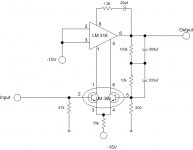
I made a schematic for the march 3 1982 article from EDN, page 111. It uses an LM318 opamp as the basis. Couldn't scan it as I used felt tip pen on it while I was making the circuit..
From what I can recall, they tied both input pins to the -15 volt rail to disable them, and replaced the input pair with the lm394 low noise pair, connecting them to the balance/comp pins.
The 100K and 10K are specified as low noise.
Cheers, John
Attachments
Re: followup schematic
I think that's the same schematic as in Nat Semi ap note 222 and 229 -- the EW article uses all sections of the LM or SSM as a "base spreader" -- not as a differential amplifier.jneutron said:I made a schematic for the march 3 1982 article from EDN, page 111. It uses an LM318 opamp as the basis. Couldn't scan it as I used felt tip pen on it while I was making the circuit..
From what I can recall, they tied both input pins to the -15 volt rail to disable them, and replaced the input pair with the lm394 low noise pair, connecting them to the balance/comp pins.
The 100K and 10K are specified as low noise.
Cheers, John
Re: Re: followup schematic
My 1990 copy of the PMI "Audio Handbook" goes into more detail, with some nice schematics using the SSM 2210 and SSM 2220.
They present a 500 pV/sqr Hz amplifier using 3 SSM 2210's and an OP-27 (strangely, they use an led as a zener feeding the input pair constant current source?).
They also show a 320 pV/sqr Hz amp using 3 SSN 2220's and an OP-27E. Again, with that led..
Cheers, John
jackinnj said:
I think that's the same schematic as in Nat Semi ap note 222 and 229 -- the EW article uses all sections of the LM or SSM as a "base spreader" -- not as a differential amplifier.
My 1990 copy of the PMI "Audio Handbook" goes into more detail, with some nice schematics using the SSM 2210 and SSM 2220.
They present a 500 pV/sqr Hz amplifier using 3 SSM 2210's and an OP-27 (strangely, they use an led as a zener feeding the input pair constant current source?).
They also show a 320 pV/sqr Hz amp using 3 SSN 2220's and an OP-27E. Again, with that led..
Cheers, John
Re: Re: Re: followup schematic
Not strange at all. LEDs make very quiet voltage references. I use far more red LEDs as voltage references than as indicators.
jneutron said:Strangely, they use an led as a zener feeding the input pair constant current source?
Not strange at all. LEDs make very quiet voltage references. I use far more red LEDs as voltage references than as indicators.
Re: Re: Re: Re: followup schematic
Ah, nice to know. For some reason, I had thought led's were very noisy. I believe it was probably from something that Risch had written and I did not think to question..😕
Cheers, John
EC8010 said:
Not strange at all. LEDs make very quiet voltage references. I use far more red LEDs as voltage references than as indicators.
Ah, nice to know. For some reason, I had thought led's were very noisy. I believe it was probably from something that Risch had written and I did not think to question..😕
Cheers, John
EC8010,
Is the red LED a personal preference or does it have different electrical properties? The reason I ask is that we can find red LEDs in the market with red lenses or clear ones. I know that clear lens LEDs emit different colors by using different metal combinations, but I am not sure if their behavior in a circuit is noticeably different.
Is the red LED a personal preference or does it have different electrical properties? The reason I ask is that we can find red LEDs in the market with red lenses or clear ones. I know that clear lens LEDs emit different colors by using different metal combinations, but I am not sure if their behavior in a circuit is noticeably different.
It's an electrical difference. LEDs produce light by momentarily exciting electrons into a higher energy orbit. As the electron falls back from this unstable orbit, it releases a photon of light. The higher the orbit, the higher the energy, the shorter the wavelength of light emitted. What this means in practice is that blue LEDs (short wavelength) require a higher voltage than red (long wavelength).
I have found by experimentation that LEDs with higher forward voltages have higher slope resistance, so I favour cheap red LEDs as voltage references. Cheap, because they're older technology and tend to be lower forward voltage and slope resistance than more modern efficient LEDs. There's been quite a bit of discussion about this on the tubes forum. The upshot is that experiment shows that for lowest slope resistance, you want a red LED that doesn't produce much light per mA of current. If anyone can come up with a physical explanation for why this is so, I'd be glad to hear it.
I have found by experimentation that LEDs with higher forward voltages have higher slope resistance, so I favour cheap red LEDs as voltage references. Cheap, because they're older technology and tend to be lower forward voltage and slope resistance than more modern efficient LEDs. There's been quite a bit of discussion about this on the tubes forum. The upshot is that experiment shows that for lowest slope resistance, you want a red LED that doesn't produce much light per mA of current. If anyone can come up with a physical explanation for why this is so, I'd be glad to hear it.
- Status
- Not open for further replies.
- Home
- Source & Line
- Analog Line Level
- Is EW seeking to redeem itself -- RIAA amp with SSM2220's