Does class D amplifier suitable for 60Hz potential transformer?
Hi , Hope this post find you well. My intention is to make an 3-phase power calibrator ! Similar to this link, Page not found My current AMP design might be class AB type. I am not worried to much about PWM generation ruther I am thinking how can I move class AB to Class D amplification.
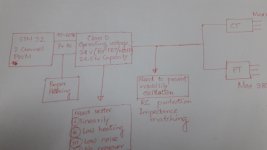
A lot of the design effort relates to maintaining linearity and avoiding crossover distortion. 2 amplifiers( current, voltage) output will feed to CT and PT! Lets consider load will be connected in their output!
REQUIRMENTS :
1. The amp input should be plus and minus 7volt AC, 45-65Hz( 1 Hz has been converted to 1024)
2. Amp operating voltage should be more or less 24v.
3. 2 channel signal (not sure PWM) should be use , one for current, one for voltage.
4.Can run current transformer(input 16.5 V/1.5 A) and potential Transformer (input15v/2A). PT output may be 15VAC.
5. If possible both voltage and current amplification is required in one IC.
6. Both positive and negative half signal should be amplify. ( take a look bellow For CT, current transformer primary winding has 80turns, 16.5 V/1.5 A, secondary has 20Turns, 4.125v/6A output! For PT, Potential transformer, Primary has 80turns, 15v/2A rating input, secondary has centertap! At secondary 960turns, 360v/0.332 A and 960turns 180v/0.166A output.
Hi , Hope this post find you well. My intention is to make an 3-phase power calibrator ! Similar to this link, Page not found My current AMP design might be class AB type. I am not worried to much about PWM generation ruther I am thinking how can I move class AB to Class D amplification.
A lot of the design effort relates to maintaining linearity and avoiding crossover distortion. 2 amplifiers( current, voltage) output will feed to CT and PT! Lets consider load will be connected in their output!
REQUIRMENTS :
1. The amp input should be plus and minus 7volt AC, 45-65Hz( 1 Hz has been converted to 1024)
2. Amp operating voltage should be more or less 24v.
3. 2 channel signal (not sure PWM) should be use , one for current, one for voltage.
4.Can run current transformer(input 16.5 V/1.5 A) and potential Transformer (input15v/2A). PT output may be 15VAC.
5. If possible both voltage and current amplification is required in one IC.
6. Both positive and negative half signal should be amplify. ( take a look bellow For CT, current transformer primary winding has 80turns, 16.5 V/1.5 A, secondary has 20Turns, 4.125v/6A output! For PT, Potential transformer, Primary has 80turns, 15v/2A rating input, secondary has centertap! At secondary 960turns, 360v/0.332 A and 960turns 180v/0.166A output.
Attachments
Last edited:
Thank you to join here.The link is dead.
take a look that missing link... [wiki=https://us.flukecal.com/products/ele...wer-calibrator]%[/wiki]
Class D amplifiers approximate voltage sources, they won't take kindly into a CT load.
Thank you sir. Kindly give some circuit examples.🙂
How would you connect such 60Hz step up transformer ? Should it be H-bridge or BTL !! LC filter is visible here! in my case the primary side impedance is 0.00117ohm. People says , Audio amp can usable for 2- 16ohm load! While it was connected to Class AB output , a 10 ohm along with 0.33uF in series RC filter was connected parallay to primary. Looking at the datasheet "PWM frame rate selectable for AM interference is in kHz range " Does it compatible ?
Attachments
Librairie "TEXAS INSTRUMENTS - UNITRODE" et "Notes d'applications diverses", octobre 2013.
Download anything to do with the UCX637 DC motor controller. In particular this one.
https://www.thierry-lequeu.fr/data/SLUA137.pdf
Your CT/PT becomes the motor. Include an inductor in the primary circuit. Use current mode control. If you don't get it don't ask.
Download anything to do with the UCX637 DC motor controller. In particular this one.
https://www.thierry-lequeu.fr/data/SLUA137.pdf
Your CT/PT becomes the motor. Include an inductor in the primary circuit. Use current mode control. If you don't get it don't ask.
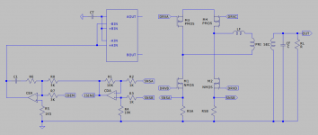
Conceptually something like the picture. CDA, a differential amplifier, reconstructs the sinusoidal bridge current from RSA and RSB. The Current error amplifier, CEA, takes the ISENSE feedback signal and compares it to the, sinusoidal current, demand signal driving the PWM comparators in the 3637.
C1 and R6 values are selected to achieve slope matching. You'll have to do a search on that subject. It sets the maximum gain in the CEA, R6/R8 in addition to that via the sense resistors and differential amplifier, and you place the C1/R6 zero at half the crossover frequency.
C1 and R6 values are selected to achieve slope matching. You'll have to do a search on that subject. It sets the maximum gain in the CEA, R6/R8 in addition to that via the sense resistors and differential amplifier, and you place the C1/R6 zero at half the crossover frequency.
Attachments
Very impressive ! Bridge type need to think!
I was messing around for a solution.
Looking at your circuit and reference, I can guess that why my Class AB had "voltage or current booster".
For the time being lets discuss issues like,
1. Low frequency and high frequency phase shifts caused by a transformer will occur if the transformer is inside the negative feedback loop (when the output of the transformer provides the negative feedback). Then the amplifier must be compensated for these phase shifts.A transformer causes a phase shift at low frequencies caused by its inductance.
2. A product with a Class-D audio power amplifier (APA) driving an output transformer with inadequate low-frequency performance may shut down when its output is stepped from zero to maximum at the start of a sine cycle. Shutdown is triggered by short circuit protection (SCP), after the first half cycle of the sine output. The root cause is saturation of the transformer core.
For the time being lets discuss issues like,
This sounds like a Student Project.
Yes...Let's (not).
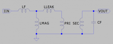
Picture of ideal transformer with input filter inductor, LF, and output filter capacitor, CF. You will be driving the transformer with what is effectively a current source. That is the LF inductor current as controlled by the 3637. It's a handy IC to get the job done. Oh it also has a current limit function.
You saturate the transformer, LMAG, if you apply too high a DC current in the primary. Let's say you use 100mR current sense resistors.
http://www.ti.com/lit/ds/symlink/lm324-n.pdf
Input Offset Voltage is specified as 2mV, 3mV max. That equates to a possible 30mA DC bias in the transformer. Input Offset Current is specified as 5nA, 30nA max. That's 30uV across 1K or 300uA in the transformer. Neither of those will be the end of the world. Otherwise you can more or less ignore LMAG because it will be big compared to LF.
LLEAK appears in series with LF so it actually helps but it will be small compared to LF. Current in LLEAK will be the same as that in LF and you are controlling that current so again you really do not care.
Basically the transformer disappears in the current loop. The inductor disappears in the current loop as well. You end up with a current source driving the output filter capacitor, CF, and the load. The voltage response is first order and easy to compensate.
By all means get data on the lump of iron you expect to use but you are more likely to be concerned about winding losses due to ripple current rather than anything else. Rather than fret over them your biggest headache will be designing LF.
https://www.tdk-electronics.tdk.com...2ba503/ferrites-and-accessories-db-130501.pdf
Picture from Page 403.
https://www.tdk-electronics.tdk.com/inf/80/db/fer/etd_29_16_10.pdf
Attachments
Last edited:
Yeap, you can say whatever you like. But, looking for something that makes money!This sounds like a Student Project.
Do you wanna make it for DC? Does it make sense that 7v ac, 45 to 60Hz input signal should fed to ClassD's input? I beg pardon, If I am wrong.if you apply too high a DC current in the primary.
Basically the transformer disappears in the current loop. The inductor disappears in the current loop as well. You end up with a current source driving the output filter capacitor, CF, and the load. The voltage response is first order and easy to compensate.
Your reference "SLUA137" says
"The function of a power amplifier is to regulate the flow of energy from a power supply to a load,
PHP:
under the control of an input signalI think my input signal has already been proceeed by , http://www.ti.com/lit/ds/symlink/dac8812.pdf
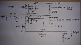
My present Class AB works well, but generating huge heat! People say it may cause "crossover distorsion" Its feedback opamp is 551, input series RC element is 13k, 1uF. Feedback parallel element may be 4.7 k, .33uF. Output has .33u and 10ohm series RC.
I am using TIP147, TIP142, C1815, A1015. They are properly biasd like cascaed 3 stage, may be AB class network. More symmetric way, like one pairs AB class output is connected to others pair. Last pairs base is connected to first pairs base! At last a voltage divider of 5 ohm has been made between 2nd and 3rd outputs!
1. My voltage and current amp circuit is slightly different.
2. In voltage amp, at OPA551, input signal is feed with reference to " ground". A series RC element 1k, 1uF after that a 220k ( one end grounded) are connected to " non inverting" input. Also a 220k one end ground is conneted to"inverting" input. A parallel RC element 270k, 0.33uF(may be) is connected to feedback path. 10 ohm, 0.1 uF RC element in series also appears in the output of the amp! Output signal also has ground reference.
3. In current amp, at OPA551, input signal is feed with reference to " ground". A series RC element 13k, 1uF after that a 1k ( one end grounded) are connected to " non inverting" input. Also a 1k one ended gound is also conneted to "inverting" input. A parallel RC element (4.7k and 47uF) is connected to feedback path. 10 ohm, 0.1 uF RC element in series are also appears between the output of the amp! In this case 2 shunt element 5W 0.5 ohm are connected and grounded in output side. No reference ground output here!
Attachments

Nope. A DC voltage on the transformer primary is the antitheses of a good idea. It will drive the core into saturation.
For your inductor going a bit backwards...
Taking your 15V/2A example. Generally you operate wire at a current density of 4A/mm^2 so for 2ARMS you need a wire area of 0.5mm^2 which is an uninsulated diameter of 0.8mm. AWG 20 has an insulated diameter of 0.876mm.
The ETD29 bobbin winding width is 19.4mm so one layer of wire gives you 22 turns. The winding height is (21.8-10.8)/2 or 5mm which gives you 5 layers. Your fully wound core ends up with 110 turns.
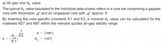
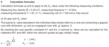
These things are either sold as halves or sets. A set comprises a gapped half and an ungapped half. You want two gapped halves. The largest gap is 1mm. Two of those gives you a 2mm gap but you have to calculate the resulting Al value. Pictures again.
s = (Al/K1)^(1/K2)
logs = (1/K2)log(Al/K1)
K2logs = log(Al/K1)
s^K2 = Al/K1
Al = K1s^K2
K1 =124
K2 = -0.7
S = 2mm
Al = 76.33
With 110 turns your inductance is 110^2 * 76.33E-9 or 923uH. Check for saturation value...
Ipk = NBpkAe/L
Bpk = 400mT
Ae = 76E-6
L = 923uH
Ipk = 3.6A
2A RMS is 2.83A peak. You allow for 20% ripple or about 600mA. That's peak to peak or 300mA peak. Absolute peak is 2.83 + 0.3 or 3.13A vs 3.6A so you have some margin for overload.
15VAC is 21.2V peak so use +/-25V [50V] for your bridge. That exceeds the voltage rating of the 3637 so you will have to generate separate supplies for it, dropped from the +/-25V [50V] bridge supply. Supplies and signal referencing are always a headache.
Anyway... You want 50V applied across your inductor to result in a change in current in your inductor of 600mA.
dI = VinTon/L
Ton = LdI/Vin
L = 923uH
dI = 0.6A
Vin = 50
Ton = 11uS
This gives a period of 22us so your bridge switching frequency, Fs, is 45KHz. This is also the frequency that you set the 3637 to. It does not work like a normal bridge driver where Ft = Fs/2.
More later.
For your inductor going a bit backwards...
Taking your 15V/2A example. Generally you operate wire at a current density of 4A/mm^2 so for 2ARMS you need a wire area of 0.5mm^2 which is an uninsulated diameter of 0.8mm. AWG 20 has an insulated diameter of 0.876mm.
The ETD29 bobbin winding width is 19.4mm so one layer of wire gives you 22 turns. The winding height is (21.8-10.8)/2 or 5mm which gives you 5 layers. Your fully wound core ends up with 110 turns.
These things are either sold as halves or sets. A set comprises a gapped half and an ungapped half. You want two gapped halves. The largest gap is 1mm. Two of those gives you a 2mm gap but you have to calculate the resulting Al value. Pictures again.
s = (Al/K1)^(1/K2)
logs = (1/K2)log(Al/K1)
K2logs = log(Al/K1)
s^K2 = Al/K1
Al = K1s^K2
K1 =124
K2 = -0.7
S = 2mm
Al = 76.33
With 110 turns your inductance is 110^2 * 76.33E-9 or 923uH. Check for saturation value...
Ipk = NBpkAe/L
Bpk = 400mT
Ae = 76E-6
L = 923uH
Ipk = 3.6A
2A RMS is 2.83A peak. You allow for 20% ripple or about 600mA. That's peak to peak or 300mA peak. Absolute peak is 2.83 + 0.3 or 3.13A vs 3.6A so you have some margin for overload.
15VAC is 21.2V peak so use +/-25V [50V] for your bridge. That exceeds the voltage rating of the 3637 so you will have to generate separate supplies for it, dropped from the +/-25V [50V] bridge supply. Supplies and signal referencing are always a headache.
Anyway... You want 50V applied across your inductor to result in a change in current in your inductor of 600mA.
dI = VinTon/L
Ton = LdI/Vin
L = 923uH
dI = 0.6A
Vin = 50
Ton = 11uS
This gives a period of 22us so your bridge switching frequency, Fs, is 45KHz. This is also the frequency that you set the 3637 to. It does not work like a normal bridge driver where Ft = Fs/2.
More later.
Attachments

Nope. A DC voltage on the transformer primary is the antitheses of a good idea. It will drive the core into saturation.
For your inductor going a bit backwards...
Taking your 15V/2A example. Generally you operate wire at a current density of 4A/mm^2 so for 2ARMS you need a wire area of 0.5mm^2 which is an uninsulated diameter of 0.8mm. AWG 20 has an insulated diameter of 0.876mm.
The ETD29 bobbin winding width is 19.4mm so one layer of wire gives you 22 turns. The winding height is (21.8-10.8)/2 or 5mm which gives you 5 layers. Your fully wound core ends up with 110 turns.
These things are either sold as halves or sets. A set comprises a gapped half and an ungapped half. You want two gapped halves. The largest gap is 1mm. Two of those gives you a 2mm gap but you have to calculate the resulting Al value. Pictures again.
s = (Al/K1)^(1/K2)
logs = (1/K2)log(Al/K1)
K2logs = log(Al/K1)
s^K2 = Al/K1
Al = K1s^K2
K1 =124
K2 = -0.7
S = 2mm
Al = 76.33
With 110 turns your inductance is 110^2 * 76.33E-9 or 923uH. Check for saturation value...
Ipk = NBpkAe/L
Bpk = 400mT
Ae = 76E-6
L = 923uH
Ipk = 3.6A
2A RMS is 2.83A peak. You allow for 20% ripple or about 600mA. That's peak to peak or 300mA peak. Absolute peak is 2.83 + 0.3 or 3.13A vs 3.6A so you have some margin for overload.
15VAC is 21.2V peak so use +/-25V [50V] for your bridge. That exceeds the voltage rating of the 3637 so you will have to generate separate supplies for it, dropped from the +/-25V [50V] bridge supply. Supplies and signal referencing are always a headache.
Anyway... You want 50V applied across your inductor to result in a change in current in your inductor of 600mA.
dI = VinTon/L
Ton = LdI/Vin
L = 923uH
dI = 0.6A
Vin = 50
Ton = 11uS
This gives a period of 22us so your bridge switching frequency, Fs, is 45KHz. This is also the frequency that you set the 3637 to. It does not work like a normal bridge driver where Ft = Fs/2.
More later.
Dont you mean "Transformers do not pass direct current (DC), and can be used to take the DC voltage (the constant voltage) out of a signal while keeping the part that changes (the AC voltage)"
My one is toroidal type PT or CT Toroidal Transformers Manufacturer from New Delhi
Since current is a big problem for driving CT, then like your advice SMPS/bridge type could be selected.
I did see system falls for PT of 100V, Class-D Amplifier TPA3116D2 driving 100V audio transformer - Audio forum - Audio - TI E2E support forums
And also here,TPA3245: OCP - Audio forum - Audio - TI E2E support forums
Lets compare those circuit with your referance before I go to your calculation.
Uhm. Yes transformers do not transmit DC voltage. No they can not be used to remove a DC voltage component. Look back at the model. If you place a DC voltage on the primary current ramps up in LMAG until the core saturates and your transformer no longer acts as a transformer. The primary becomes a short circuit.
The other examples you quote from TI appear to be people thinking the wrong way around or dealing with different applications. A Class D amplifier is designed to behave as a voltage source to drive a loudspeaker. The example with a transformer in between the amplifier and loudspeaker is probably a 70V line system. The problem appears to be that the amplifier, a voltage source, is tripping at initial turn on.
Transformers have a thing called Remanence which is a thing whereby when you turn them off there is a residual flux in the core that might leave it close to saturation. When you next turn it on and drive it with a voltage source in the wrong direction you take the core into saturation. LMAG drops to zero and you end up with a short circuit being driven by a voltage source which either blows up or goes into current limit.
You don't want to drive a loudspeaker with music you want to drive a transformer with a 50/60Hz sine wave. The 3637 is going to do that with a current, 2A RMS, sine wave, as opposed to a voltage one. It is very likely that if you try to short circuit it either deliberately or as a result of the transformer doing something wrong it will just sit there happily driving it with a 2A RMS sine wave and nothing else will happen.
We could avoid this issue, because those IC's are more smart. RC time constants are internally fixed. Some of them has "current sencing" facilities beside short circuit.The problem appears to be that the amplifier, a voltage source, is tripping at initial turn on.
Is a charged capacitor a voltage source? Is a charged inductor a current source? Is there any difference between them and "true" electrical sources?
When you next turn it on and drive it with a voltage source in the wrong direction you take the core into saturation. LMAG drops to zero and you end up with a short circuit being driven by a voltage source which either blows up or goes into current limit.
Well said even very elementery facts! Lets think how the AMPS are behaves. If you could compare the ClassAB, A, B you could see conduction angle facts!
When your signal is much slower, then why dont we think for others!
The conduction angle is not a factor in such case as the direct input signal is changed with a variable pulse width. In this Class D amplifier system,
the linear gain is not accepted as they work just like a typical switch which have only two operations, ON or OFF.
Yes, I am agree with you. Most probably the challenge is to control facilities, since my system has instruction from central stm32!The 3637 is going to do that with a current, 2A RMS, sine wave, as opposed to a voltage one


Last edited:
- Home
- Amplifiers
- Class D
- Is class D amplifier suitable for 60Hz potential transformer?