So, a year or so ago, I got this idea about trying to build a high-power tube-sound instrument amp by driving a low-power tube amp into a transistor amp, then feeding the output current back through to the tube amp, like in the attached schematic.
Would a Class-D amplifier have the response necessary to make this work, or do I need to go for Class-AB or -B?
Thanks,
- Alex
Would a Class-D amplifier have the response necessary to make this work, or do I need to go for Class-AB or -B?
Thanks,
- Alex
Attachments

Well you're not the only one to have this idea, it gets kicked around a lot.
And it does actually work, after a fashion. You can get some of the tube amp sound by using it as what is essentially a line stage or preamp. You may not like the results, but that's a different story. You might even end up with too much tube flavor.
I'm not quite sure why you would want the the feedback loop, but maybe someone else here could comment.
Perhaps I should elaborate more. The purpose of the external feedback loop is to give the tube amp the same load it would have if it were driving speakers. By drawing a proportional amount of current from the tube amp that is being drawn from the transistor amp, I simulate the load of the speakers exactly to the tube amp.
Yeah, OK.
But really you just need a load resistor for the tube amp. Use whatever, 4, 8, 16 ohms. The load and the taps you use will determine the sound of the amp, the harmonic structure. Play around with different loads to find the sound you like. You'll only be driving about 2-3 volts out of the tube amp, so no worries.
But really you just need a load resistor for the tube amp. Use whatever, 4, 8, 16 ohms. The load and the taps you use will determine the sound of the amp, the harmonic structure. Play around with different loads to find the sound you like. You'll only be driving about 2-3 volts out of the tube amp, so no worries.
A speaker is not just a resistor. The impedance of a speaker system changes drastically with frequency, as does the effective output impedance of the tube amp. The characteristic sound of a tube amp is partially defined by the interaction between the speaker cabinet, output transformer, and whatever feedback there may be in the amp.
Being that a speaker is a reactive device, only an active feedback such as this will properly pass on the load.
So, the root question of this thread is: Will the output voltage of a Class-D amp track the input voltage fast enough for a loop such as this to effectively represent the impedance and phase of the load?
Last edited:
Hey, I'm thinking of this, too.
Not for the 'tube' sound, but trying to tune the system Q with the much higher than normal output impedance, which is very useful for low Q woofers in OB.
I'm not familiar with class D (T) circuits😱 With some shallow studies on the datasheets and manuals, it seems the half bridged (single ended) design is much easier to mod. Now I'm playing with Amp 6 which is full bridged thus floated outputs. So a differetial amp is essential to isolate both ends (of feedback loop). I'd guess UcD amps are much easier to play with -- single ended (grounded) output, and a negative input, how convenient!
Another idea, is it possible to use a line level transformer to get the differential signal (a part of the output current) and feedback to the input (which is marked negative in Amp 6)? Primary is connected to both ends of the series resistor at output, and secondary is connected to the input (via a resistor) and the bias pin. Will this work?
I believe that's done, in reverse, on some hifi amps to compensate for resistance in the speaker wires.
That's different from what I'm doing, though. You want the power amp fed-back from a virtual point as if there were a resistor in series with the speaker. I think I explained my intent well in the previous post. If not, ask further questions and I'll try to explain better.
That's different from what I'm doing, though. You want the power amp fed-back from a virtual point as if there were a resistor in series with the speaker. I think I explained my intent well in the previous post. If not, ask further questions and I'll try to explain better.
I believe that's done, in reverse, on some hifi amps to compensate for resistance in the speaker wires.
For isolating output current measurements from input, just use a balanced-input opamp circuit. That's what U1A and R2-5 do in my circuit above. Ignore R1, and the output of U1A will be the voltage across R6 using the other end of R2 as a reference.
That's different from what I'm doing, though. You want the power amp fed-back from a virtual point as if there were a resistor in series with the speaker. I think I explained my intent well in the previous post. If not, ask further questions and I'll try to explain better.
A speaker is not just a resistor. The impedance of a speaker system changes drastically with frequency,
Yeah, OK. But IMO you are way over thinking this. Sure, you could come up with some active or passive network to imitate the load or sound of the speaker connected to the amp, but why? Will it really be better? I doubt it.
A simple load on the amp and some EQ if you want it should get you 99% of the way there. Why not at lest start out simple to hear if you like it or not?
Use this to dummy load the tube amp
Speaker load
Take the output off of R1 through to feed the output amp.
As mentioned, there are already commercial amps that do just this.
Better yet, put a speaker in an isolation box with a mic in it and feed the mic to the class-d through a mic preamp. You really need crappy speakers to old mics to make this sound authentic.
Amp 6 with current feedback
This is what I did last weekend.
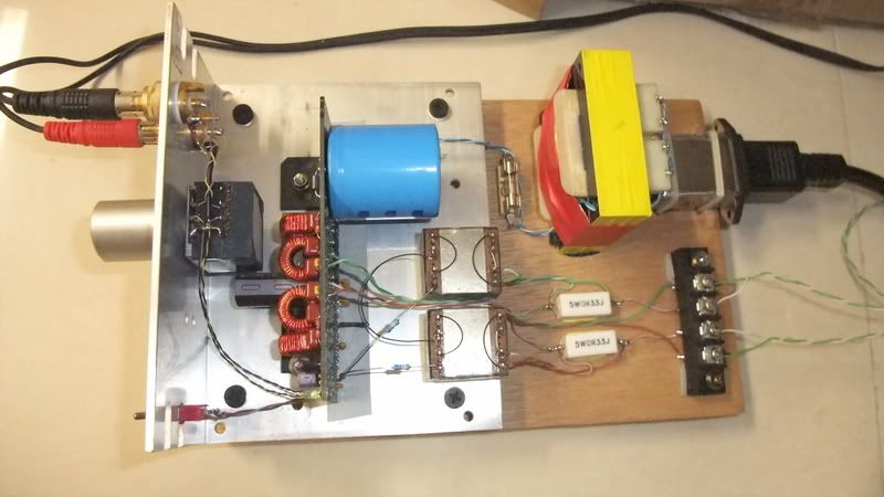
Prototype of Amp 6 kit with transformer-coupled current feedback:
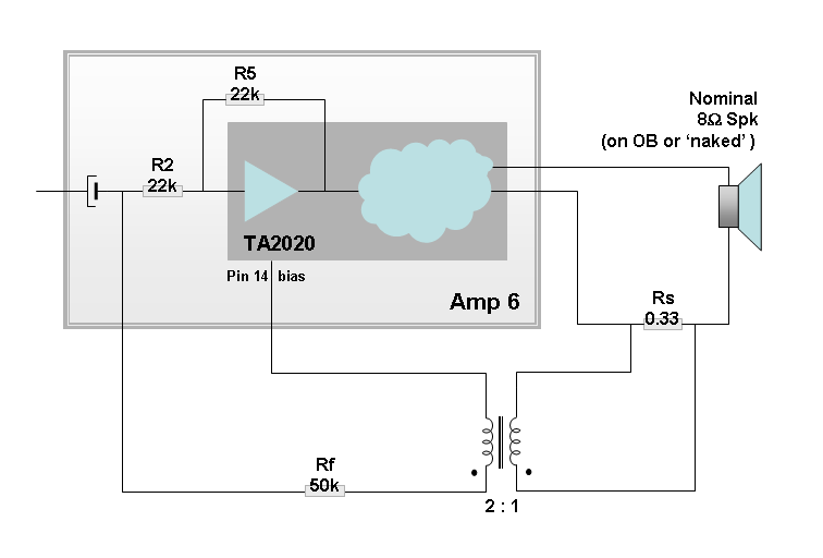
Simplified circuit:
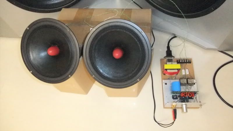
Initial crude trial:
TBH, I was fiddling with it with no clue how it would work. 😱 ....
Speakers under test are a pair of 8" wide-rangers. Just to test the basic function of the system only, since I don't know how it sounds when playing fullrange (I used it as a midrange after I cut the whizzer....). They were put on the box and basically playing naked.
At first I tried the amp without the external feedback loop. Dipole loss was compensated by the upstream digital EQ, which was quite a lot as expected.
Then I added the current feedback to raise the output impedance. I don't know if I did it right, just gave it a try. This is what I think:
Assumed in a case the output current is 1A into 8 Ohm, then it's 8V across.
Now I add a resistor of 0.33 Ohm in series with load, then there'd be 0.33 V across this resistor under 1A.
The 0.33 V is then stepped up to 0.66 V by the transformer and feed in the negative input. The amp has a voltage gain of 12, so the -0.66 V is amplified to a -7.92 V at the output....
Now the strange part, previously there should be 8V on the output. Now it's eaten up by 7.92V, so only 0.08V is left... The voltage on the output is now only 1% of the original, so may I say the output impedance is 100 times of the load? (800 Ohm!!) Hmmm... doesn't look right.... 😕
And I don't know what the 50k Rf would do to the circuit, it's there to be a 'buffer' - I don't want the input to see the low impedance of the transformer and it's reflected other side. I have no clue how it interacts to the amp. 😱 I guess there should be some voltage divisions happening here, but don't know how to calculate. I have a feeling that I'm kind of an ape playing human's stuff.
....
This is what I did last weekend.
Prototype of Amp 6 kit with transformer-coupled current feedback:
An externally hosted image should be here but it was not working when we last tested it.
Simplified circuit:
An externally hosted image should be here but it was not working when we last tested it.
Initial crude trial:
An externally hosted image should be here but it was not working when we last tested it.
TBH, I was fiddling with it with no clue how it would work. 😱 ....
Speakers under test are a pair of 8" wide-rangers. Just to test the basic function of the system only, since I don't know how it sounds when playing fullrange (I used it as a midrange after I cut the whizzer....). They were put on the box and basically playing naked.
At first I tried the amp without the external feedback loop. Dipole loss was compensated by the upstream digital EQ, which was quite a lot as expected.
Then I added the current feedback to raise the output impedance. I don't know if I did it right, just gave it a try. This is what I think:
Assumed in a case the output current is 1A into 8 Ohm, then it's 8V across.
Now I add a resistor of 0.33 Ohm in series with load, then there'd be 0.33 V across this resistor under 1A.
The 0.33 V is then stepped up to 0.66 V by the transformer and feed in the negative input. The amp has a voltage gain of 12, so the -0.66 V is amplified to a -7.92 V at the output....
Now the strange part, previously there should be 8V on the output. Now it's eaten up by 7.92V, so only 0.08V is left... The voltage on the output is now only 1% of the original, so may I say the output impedance is 100 times of the load? (800 Ohm!!) Hmmm... doesn't look right.... 😕
And I don't know what the 50k Rf would do to the circuit, it's there to be a 'buffer' - I don't want the input to see the low impedance of the transformer and it's reflected other side. I have no clue how it interacts to the amp. 😱 I guess there should be some voltage divisions happening here, but don't know how to calculate. I have a feeling that I'm kind of an ape playing human's stuff.
....
Last edited:
Try feeding the transformer in series with R5 if you can. Also, you may want to put an L-pad on the transformer so you can adjust the feedback level and listen to the effect in real time.
Question is how it worked.
At the first trial with normal Amp6 and massive EQ, to my surprise, the poor little naked 8" wide rangers were singing quite nicely. In my living room of appox. 50m^2 (& low ceiling), overall tonal balance was OK. Severe beaming is for sure, but acceptable balance could be obtained when off axis by a little angle and overall room response was also acceptable.
Because of the massive bass EQ lift in the digital domain ate up the dynamic range of the processor, so it clipped easily. I had to attenuate it quite a lot, eventually used up the -15dB range of DEQ2496. At this stage, this system produced an SPL similar to loud indoor quarrels -- I had to talk quite a lot louder then normal to fight against it. Pop music was actually quite enjoyable with good balance and dynamics. (I never know a pair of naked 8"ers can do this!)
Then the modded amp with current feedback. As mentioned I don't know how much the feedback actually is, and it did play much quieter in the midband (compared at the same volume setting of course). So at least the negative feedback did work (in a way I don't really understand). Good thing was it also needed much less bass EQ (as the goal), so the overall shelfing was shallower by 10dB or so. Higher output level at the source, lower gain at the amp, in the end they cancelled out and played to almost equal loudness and in similar balance.
I won't go into the sound quality review of this mockup, but the one with current feedback (higher Zo) didn't sound tubey at all (to me, at least). TBH, 2 setups sounded almost identical after properly EQ'ed. (It's odd and fun to see 2 naked 8"ers playing bass heavy materials with their little busy cones jumping around. The excursion might hit 4~5mm one way in my eyes.)
In a more thorough and proper setup, they should be somewhat different because of different degree of EQ. I tend to like the high Zo approach for dipole speakers and I'll try more with this little thing in my main system.
Try feeding the transformer in series with R5 if you can. ....
Thanks, but I don't understand😱
Do you mean connecting the secondary winding in seris with R5?
Thanks, but I don't understand😱
Do you mean connecting the secondary winding in seris with R5?
Yes, exactly.
So anyway, with my original question, I'm trying to add a transistor buffer that will allow this: "Speaker clank" and the "physical" sound
Maybe I should just build a UcD amp and try it, and if it doesn't work, switch to a Class-B transistor amp instead.
Maybe I should just build a UcD amp and try it, and if it doesn't work, switch to a Class-B transistor amp instead.
Hi Circuitsoft,
I feel somewhat pity that it seems nobody else is interested in adding output impedance to any amp. Please go try your idea, and let us (or only me) know the results😀 I think there's no reason why a feedback loop mod can't be applied to a class D amp (or any amps). Class D is still holding its own good, we just 'adjust' it a little to suit our application, nothing wrong.
About my little trial, I'm sorry to say I haven't tried your suggestion. Maybe they'll come to a same result in the end, but fiddling with the original feedback loop kind of scares me off.
I did re-adjust the resistors in my proto-type, though. First I raised the voltage gain by increasing the original feedback resistor (R5) to 40.2K, thus raised the gain from 12 to 12* (40.2/22) = 21.9
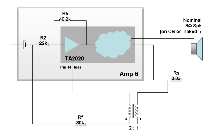
Then I figured that the added (current) feedback should probably be divided by Rf and R2. So, re-calculate the feedback of the current content would be:
Assumed: 8 V / 1 A pass through Rs => 0.33 V across
stepped up to 0.66 V on Rf, then divided by 22/(22+30) => 0.28 V on input
V (of current Fb) = 0.28 * (-21.9) = - 6.11 V
Zo : Rload = 6.11 : (8-6.11)
Zo = 6.11 / 1.88 * 8 = 26 Ohm
Now this looks more like it. No?
And the speakers under test were 'upgraded' somewhat, at least going with a 'proper' baffle. It hasn't hit to the goal, yet, but is approaching....
http://www.diyaudio.com/forums/multi-way/166850-even-cheaper-faster-ob-trial.html#post2186484
I feel somewhat pity that it seems nobody else is interested in adding output impedance to any amp. Please go try your idea, and let us (or only me) know the results😀 I think there's no reason why a feedback loop mod can't be applied to a class D amp (or any amps). Class D is still holding its own good, we just 'adjust' it a little to suit our application, nothing wrong.
About my little trial, I'm sorry to say I haven't tried your suggestion. Maybe they'll come to a same result in the end, but fiddling with the original feedback loop kind of scares me off.
I did re-adjust the resistors in my proto-type, though. First I raised the voltage gain by increasing the original feedback resistor (R5) to 40.2K, thus raised the gain from 12 to 12* (40.2/22) = 21.9
Then I figured that the added (current) feedback should probably be divided by Rf and R2. So, re-calculate the feedback of the current content would be:
Assumed: 8 V / 1 A pass through Rs => 0.33 V across
stepped up to 0.66 V on Rf, then divided by 22/(22+30) => 0.28 V on input
V (of current Fb) = 0.28 * (-21.9) = - 6.11 V
Zo : Rload = 6.11 : (8-6.11)
Zo = 6.11 / 1.88 * 8 = 26 Ohm
Now this looks more like it. No?
And the speakers under test were 'upgraded' somewhat, at least going with a 'proper' baffle. It hasn't hit to the goal, yet, but is approaching....
http://www.diyaudio.com/forums/multi-way/166850-even-cheaper-faster-ob-trial.html#post2186484
Last edited:
- Status
- Not open for further replies.
- Home
- Amplifiers
- Class D
- Is a Class D amp appropriate if you have an external feedback loop?