Hi all,
I'm working on a high power amplifier using IRS2092 with totem-pole driven pairs of IRFB4227 and +/-90V rails. So far I have everything working fairly well with low noise and THD and excellent sound quality. My issue is that at idle I feel the mosfets are getting hotter than they should. I have two channels on one board, so there are 8 fets mounted to an aluminum bar of a similar type to that used on the IR reference designs (IRAUDAMP1,7). This sink is getting to approx 55 degrees C after 30mins of the amp sitting idle, load connected and no input signal. The output filter is a 4th order type with 17uH and 11uH coils wound on T106-2 material. The inductors do not get more than slightly warm to the touch. The switching waveform looks ok, but I have not fully opimized snubbers yet. Any pointers on where to start looking would be appreciated.
I'm working on a high power amplifier using IRS2092 with totem-pole driven pairs of IRFB4227 and +/-90V rails. So far I have everything working fairly well with low noise and THD and excellent sound quality. My issue is that at idle I feel the mosfets are getting hotter than they should. I have two channels on one board, so there are 8 fets mounted to an aluminum bar of a similar type to that used on the IR reference designs (IRAUDAMP1,7). This sink is getting to approx 55 degrees C after 30mins of the amp sitting idle, load connected and no input signal. The output filter is a 4th order type with 17uH and 11uH coils wound on T106-2 material. The inductors do not get more than slightly warm to the touch. The switching waveform looks ok, but I have not fully opimized snubbers yet. Any pointers on where to start looking would be appreciated.
Attachments
You'll have to post data or pictures about the heatsink before anyone can say much. The mouting interface (bar or block) is not a heatsink.
Quiescent power consumption is good info too. If its taking 30 minutes to reach max temp you have plenty of thermal mass in the mounting block, but you're lacking surface area (Fins!) if it's getting all the way to 50C. That much is sure.
Quiescent power consumption is good info too. If its taking 30 minutes to reach max temp you have plenty of thermal mass in the mounting block, but you're lacking surface area (Fins!) if it's getting all the way to 50C. That much is sure.
Last edited:
I would only use 1 pair of devices, not 2 pair. Also, play with DT. Increase it. That should help reduce Pd but it might cause THD to get rise.
I found my 2092 design got hot at 400KHZ so I reduced it.
Have a play with deadtime too.
I use max dead time with my irfb4227's.
Have a play with deadtime too.
I use max dead time with my irfb4227's.
Hi Andrew,
The aluminum bar is 4"x1.25"x0.625" with all 8 fets mounted to one side with thermal grease and mica pads.
I understand that the heat spreader bar is not a proper heatsink, but during testing I do feel it is getting too hot in idle. My version of the IRAUDAMP7S using +/-70V and one IRFI4020 per channel uses the same aluminum bar and gets barely warm after idling all day.
AC line current draw (at 115Vac) is 150mA in standby (output stage not switching) and 360mA in idle.
Thanks!
You'll have to post data or pictures about the heatsink before anyone can say much. The mouting interface (bar or block) is not a heatsink.
Quiescent power consumption is good info too. If its taking 30 minutes to reach max temp you have plenty of thermal mass in the mounting block, but you're lacking surface area (Fins!) if it's getting all the way to 50C. That much is sure.
I am planning on fairly high current demands into 2 or 3 ohms loads, so for safety I am running two pair of output devices. I'll try increasing dead time to see if that reduces idle Pd.
Thanks!
Thanks!
I would only use 1 pair of devices, not 2 pair. Also, play with DT. Increase it. That should help reduce Pd but it might cause THD to get rise.
A few updates:
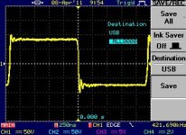
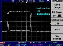
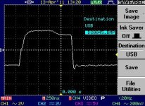
I removed the 10k Gate-Source resistors and added a turn off diode across the gate drive resistors. I also increased deadtime from DT2 to DT3 as shown in the IRS2092 app note. The amp is now idling at approx 43 degrees C instead of the 54 degrees C previously. I did not suffer any significant increase in THD. I decided to borrow a differential probe from work to have a good look at Vds and Vgs on both high and low sides.
Photos are attached for idle condition, load connected but no signal.
Any comments would be appreciated.
Thanks!
Attachments
Have you tried running through the switching loss formula for both amps to see if the dissipation checks out as expected? I don't have data on those transistors, but all other things being equal, double the transistors and increased voltage will definitely make thing hotter.
Edit: just noticed the 4227 is a much bigger transistor. I'd say everything with the heat in your case is "normal".
Edit: just noticed the 4227 is a much bigger transistor. I'd say everything with the heat in your case is "normal".
Last edited:
Sounds like you had a bit of shoot through.
You can adjust the deadtime to help with this on the 2092.
You can adjust the deadtime to help with this on the 2092.
I don't know, I have for now +/-47 with no heatsing with no problems, and fets are no more then 55C hot
I can run my 2092 amp full bore with no heatsink and that has one pair of 4227's.
Doesnt even get luke warm.
Doesnt even get luke warm.
With something like 30 mOhm the 4227 conduction losses aren't going to be much over the switching losses for moderate power into 8 Ohm. +/- 47 volts will lose almost half the power of the same output stage at +/-90.
Also, Nigel, you said you had to slow down from 400kHz to keep things cool. What frequency are you running?
Also, Nigel, you said you had to slow down from 400kHz to keep things cool. What frequency are you running?
Also, Nigel, you said you had to slow down from 400kHz to keep things cool. What frequency are you running?
I am running about 200KHz.
Switching waveform is now looking very good with the increased deadtime and I can deal with the dissipation. The next step is to tackle optimal snubbers as I am getting some nasty spikes on the power supply rails at high power levels (500W+ into 4ohms). Eva has given some excellent pointers in this area and I hope to be able to make some good headway.
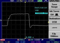
Can anyone explain the mechanism that causes the gate drive turn off undershoot? I haven't been able to dig anything up in the references I have on hand.
There are two possible sources, the most elementary one is negative di/dt on source lead and associated PCB track inductances, the other is enough series inductance in the gate loop and too little resistance in series to damp the resulting RLC. Both are rarely a problem if there is just a spike with no ringing, but protection diodes are recommended, placed from the outputs of the driver IC to the rails.
Thank you for the information Eva!
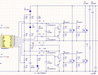
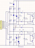
If I understand correctly, you are indicating diodes should be placed from the gate drive outputs and the high or low side rail. I have these as D6 and D7 on the attached schematic. Any suggestions on the type of diode that should be used here? I'm thinking it should be a high speed type.
Thanks!
If I understand correctly, you are indicating diodes should be placed from the gate drive outputs and the high or low side rail. I have these as D6 and D7 on the attached schematic. Any suggestions on the type of diode that should be used here? I'm thinking it should be a high speed type.
Thanks!
There are two possible sources, the most elementary one is negative di/dt on source lead and associated PCB track inductances, the other is enough series inductance in the gate loop and too little resistance in series to damp the resulting RLC. Both are rarely a problem if there is just a spike with no ringing, but protection diodes are recommended, placed from the outputs of the driver IC to the rails.
Attachments
IRS2092
Dear Ungie,
We use the IRS20957 with IRFB4227 and also the Infineon IPP320N20NG3 with 2+2 output devices.
Between pin 13 (IRS20957 and IRS2092) insert a 10 ohm resistor with a catch diode from pin 13 to -Vcc (We use 35nsec 1A 600v diode ES!J) This will prevent damage to the IC from any spikes which may "float" around.
I use a Totem driver per MOSFET so that the PNP can discharge directly to the source pin of the MOSFET.
In addition I do not lay out the totems like you have. The NPN has the gate charge resistor in its emitter and the PNP has its emitter directly connected to the gate of the MOSFET for super quick discharge.
I use higher value gate resistors (Up to 33 ohm) to lower EMI. The higher values cause no extra dissipation in the MOSFETs in practical terms.
The active discharge PNP takes care of a lot of issues.
Run the IR chip at max deadtime.
Run the oscillator at 350KHz
You may want to also try external Schottky diodes across the MOSFETs as their internal diode will be having a hard time at these rail voltages.
Steve Mantz
Zed Audio Corp.
- Status
- Not open for further replies.
- Home
- Amplifiers
- Class D
- IRS2092 High Power mosfet heat question