Then why use tubes at all?@analog_sa - yes, but this is increasingly difficult for medium-mu tubes requiring higher impedance load, not any 4-windings xfmr will work there, same goes for the choke 🙂
Speaking of harmonics, is a lost battle trying to favor one or another, in my view the best approach is aiming for lowest, period
Before any thd measurements, do the following:
Load the transformer secondary with either the real load, or at least a capacitive load close resembling the real capacitive load of the following stage intended to be driven.
Next, try to find the value of the load resistances that provides optimal damped square wave response.
Only after those steps measure distortion.
( the foregoing under the assumption that there is no meaningful grid current that would need to be accounted fore)
Measurement taken at 1kHz are a easely impressing marketing feature, but do not tell much about the real performance over the full audio bandwidth and voltage range.
What distincts a good transformer coupled stage from a less perfect is impulse behavier, and what happens under the heavy reactive load at the extremes of the audio band.
The distortion at say 20-30Hz and 8-10kHz could actually tell you something, 1kHz distortion, is in my view, almost meaningless.
Just my 2 cents
Last edited:
@gorgon53 - Thanks, but what I'm trying here is to expose how this inverter behaves out of the box, a proof of concept if you want, given that all those classic inverters out-there start with high distortion before feedback, yes, at 1kHz! See for instance Max Robinson's site angelfire.com ... From an engineering point of view is nice to have low distortion at 20Hz but in terms of music this is almost meaningless. And again, here I'm not looking for flat performance 10Hz-1MHz but a practical way to get the job done and keep it simple in the same time. As an example see the attached and judge for yourself if you can make it simpler 🙂
Attachments

Then why use tubes at all?
I like the glow, a transistor can't do that 🙂
Are 2 transformers really better than 2 capacitors to connect stages?
Short answer, yes! ... but where do you see 2 xfmrs?
Not quite: a little distraction. Most tube amps without global nfb will give 1-2% thd at 20Hz at designed transformer cutoff at rated output, this distortion is usually F2 (even harmonics sounding easier on the ear), and with 10-20dB amp global nfb, the thd will drop appropriately and lower the amplifier output impedance which provides a better system damping factor. It is important to have global nfb to dampen loudspeaker resonance, if not, quite a proportion of F2 harmonic including the amplifier output impedance creates an artifical bass effect. This is often a reason that SE amps without any global feedback often sound with a "fuller" bass or more timbre than sand s/s amps, due to uncontrolled LS resonance peaking.From an engineering point of view is nice to have low distortion at 20Hz but in terms of music this is almost meaningless.
Much in the music industry uses console mixer desks with input transformers, and with pop music, the studio or mixing engineer will often have the pre-recorded bass line played back at a higher level through the input transformer accentuating this 2nd harmonic, gated appropriately and re-mixed, is in effect to sound better in small systems. Simple ? It sells better. On larger cabinet speakers it can sound overpowering and distinctly synthetic.
It may be somewhat unmusical to mention of how many op-amps and mixing busses of most musical sound we eventually hear (except classicals) has been through, and perhaps changed....for the worse ?? What is often played isn´t always what one hears.
I prefer sitting back and listening to the exacting sound of a 2 or 3 stage P-PP amp with a large full range speaker system.
Bench Baron
With only triodes in the chain, and without multistage fb, transformer coupled has certainly some advantages over capacitive coupling.
Alone the fact that the "gridresistor" can be the low Rdc of the secondary winding is a big assurance against possible tube runaway with neg gridvoltage biasing.
Downside is mainly price, weigth, increased capacitance, phaseshift, ďelay, increased distortion do to the
decreased loadimpedanz and therefore Increased loading at the frequency extremes.
20Hz transformer distortion will propably be of little concern because it will be swamped by speaker distortion. But one should not look at the 20Hz thd alone without considering the harmonics
intermodulation with themselves and the audiosignal, things are more complicated than comparing 20Hz speaker distortion with 20Hz amp distortion.
There is no way around the fact that a transformer means addional reactive loading of the amplifier stage driving it. lncreased loading means decreased voltage swing and/or increased distortion, simple as that.
In that regard, cap coupling has an advantage, at least up to the max Ub the tube can handle or the ps provide.
Same goes for chokes, alltough in my opinion, the advantages of semiconductor CCS easely is not what is often presumed, the high impedance at dc can be a far cry of the real impedanz at higher frequencies. Additionally, circuit depended, the voltage modulated capacitance, especially with a semiconductor ccs, can become a problem during high voltage excursions, and chokes could be an overall better choice.
As always, multiple choices, each has its own strength and weaknesses.
So yes, transformers and chokes are simple to apply, but anything else about them is not simple at all.
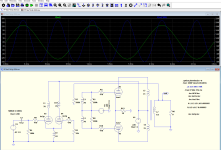
@benchbaron - I see you're quite pasionate about those harmonics, can you read for me please the % THD of HD2 and HD3 below, 20Hz, please?
This graph is just one phase (for easy reading) for a 6DJ8/6N23P.

This graph is just one phase (for easy reading) for a 6DJ8/6N23P.
So yes, transformers and chokes are simple to apply, but anything else about them is not simple at all.
Tell me about it! 🙂 I'm playing with xfmrs for some decades now, since I've compared a simple SE amp with and without inductive coupling...
As you can see, do to increased reactive loading at 20Hz the second harmonic is about 100 , h3 almost 180 times higher than at 1kHz.
As you can see, do to increased reactive loading at 20Hz the second harmonic is about 100 , h3 almost 180 times higher than at 1kHz.
This is a profoundly wrong way of thinking, human hearing is not LINEAR but logarithmic (more or less - funny, I'm thinking at Fletcher-Munson now)... keep also in mind even harmonics cancel and absence of GNFB!
Since you have analyzed the graph, I repeat my question: what's the %THD at 20Hz for HD2 and HD3?
Last edited:
Yes.... I experimented the differential PP driver for 300B SE. I used the LM317 CCS at the common cathode instead of choke. The result was really good.
I believe 6N3P using the resistance of the choke to establish the cathode bias voltage. Hope it will provide the right bias for the tube.
Johnny
I believe 6N3P using the resistance of the choke to establish the cathode bias voltage. Hope it will provide the right bias for the tube.
Johnny
Nobody says can't be put in series with the right resistor... 🙂I believe 6N3P using the resistance of the choke to establish the cathode bias voltage. Hope it will provide the right bias for the tube.
Reactive load for interstage transformers is not a good way to see it. It is the current the tube has to put into the the load. If the tube is linear in the range where it is supposed to work there is no problem whatsoever. It's not an output stage where tubes are required to output the max current they can.As you can see, do to increased reactive loading at 20Hz the second harmonic is about 100 , h3 almost 180 times higher than at 1kHz.
In this case, being a PP transformer, if one wants even lower distortion also at 20Hz can just use a more linear tube and/or working at higher current. Don't need a lot more to drop THD significantly. On top of this, if I read it right, the dominant 1% H2 in the pictures above will go away because of the inherent PP cancellation and so it will be quite low overall already with the 6n3p....
Last edited:
Assuming your signal generator has no distortio, take the differenz between the output and the harmonic you are interrested in db, divide by 20, use a pocket calculator to take the inverse log, multiply by 100 to get the percentage.
As to Fletcher Munson, thats exactly why i said, forget the fundamental, look at the harmonics and theyr intermodulation with the signal (music contains much more than just bass notes). Funny you did not get my point alltough you are aware of the ears much higher sensitivity at medium frequencies.
B.t.w., in my view, harmonics should be weigthed, thd is totally misleading in that respect.
On first post image and on schematics.Short answer, yes! ... but where do you see 2 xfmrs?
Yes, but since we have Internet and our pocket calculator has dried batteries we can check a "dB to percent" calculator online... I'm not worried about HD2 so let's check HD3; 31.9+21.32=53.22 dB span = 0.21% THDAssuming your signal generator has no distortio, take the differenz between the max output in db and the harmonic you are interrested in, divide by 20 use a pocket calculator to take the inverse log, multiply by 100 to get the percentage.
again, 0.21% HD3 at 20HZ, more than 20Vrms output!!!
In this case, being a PP transformer, if one wants even lower distortion also at 20Hz can just use a more linear tube and/or working at higher current. Don't need a lot more to drop THD significantly
I couldn't say it better...
You can look at it any way you want, but any triode will have lower distortion the smaller the relative.current load variation, period.Reactive load for interstage transformers is not a good way to see it.
Looks like PP but is not, as you can see second harmonic is not cancelled. The first triode has partial anode and cathode load. The second triode is grounded grid connected, cathode driven. No cancelling of tube/load related h2 unless you drive both grids..if I read it right, the dominant 1% H2 in the pictures above will go away because of the inherent PP cancellation and so it will be quite low overall already with the 6n3p....
The transformer itself can only produce a second harmonic if dc magnetisated due to some imbalance.
The choke has dc magnesitation and therefore will add unavoidable h2 thqt will show up in the output and cannot be cancelled.
With both grid driven, there ideally would not be any current variation an therefore any choke induced distortion, but then again, you would not need any choke at all.
To improve this circuit, ditch the choke and use a balanced driver, a 50/50 split load triode or jfet will do (cant remember how its called in english)
Last edited:
- Home
- Amplifiers
- Tubes / Valves
- Iron Schmitt phase inverter - lowest THD seen