sorry, I missed that comparator is double. TP4 only is wrong. rest is good step to step to adjust your amplifier.🙂
Hello,
last night I was tired of work.
TP4 is correct for testing.
as I said before, your schedule is only good in theory, not in practice.
I do not know who did this scheme.
first error is +12 V on VDD of IR2110. this pin is created to give the possibility to adjust the threshold of the right input.
LM360 at +5 V (+ internal resistor on the positive side) +2N5401 + Res, (can not drive IR2110, creating too unbalanced and critical segment PWM).
Put +5 V VDD ref to COM pin.
Even first stage contains not a good solution (not drag offset up to first stage). amplifier closed loop inside the FB.
OK, now you can go to study.🙂
You arrogance is true problem..not amplifier.
new drivers are arrived.
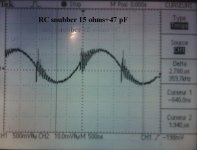
i ve made a mistake with capacitor value for MOS snubber.
now it's 15 ohms+220 pF (ceramic )
i will try with lower capacitor value to decrease ringing correctly.
feet comparator capacitor value are added (47 pF)
rising time is 3.5 KV/uS
it's in a good way.
i ve made a mistake with capacitor value for MOS snubber.
now it's 15 ohms+220 pF (ceramic )
i will try with lower capacitor value to decrease ringing correctly.
feet comparator capacitor value are added (47 pF)
rising time is 3.5 KV/uS
it's in a good way.
Attachments
Last edited:
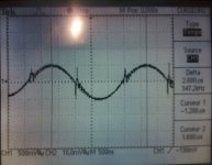
the RC snubber tries with another values is less efficient.
on the first picture RC= 15 ohms+47 pF
i've tried with 15 ohms+100 pF,~ same result.
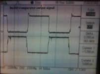
output of comparator is not so bad,the feedback on the layout is not on the same way for each foot of the commparator
rising and falling time on the inverting output of comparator is a little bit different,i'm waiting for new ones.
maybe,that can explain asymetry ringing on output power stage.
THD will be done right now.
on the first picture RC= 15 ohms+47 pF
i've tried with 15 ohms+100 pF,~ same result.
output of comparator is not so bad,the feedback on the layout is not on the same way for each foot of the commparator
rising and falling time on the inverting output of comparator is a little bit different,i'm waiting for new ones.
maybe,that can explain asymetry ringing on output power stage.
THD will be done right now.
Attachments
Last edited:
now all troubles are fixed
i will post scope pictures tomorow.
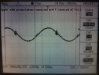
ground plane was connected to -V (as IR note application),audio signal on input comparator was affected by EMI.
now ground plane is connected to 0 V power supply,audio signal (input comparator is very clean )
output audio signal too
i will post scope pictures tomorow.
ground plane was connected to -V (as IR note application),audio signal on input comparator was affected by EMI.
now ground plane is connected to 0 V power supply,audio signal (input comparator is very clean )
output audio signal too
Last edited:
ok,
I'm glad you've put the result of your work.🙂
There are many small problems to be solved.
I see that the noise could be the power supply?. or probably too low "PSRR"
you have fed at Vdd +5 V? This is correct.
lm360 has directly on the pins (VCC) bypass? (2 capacitors for side)
ok, keep me updated on future developments of your amplifier.
Attachments

good,
VDD to +5 V, equal potential Vcc lm360 not ... my invention! this is the right way to design .. (I think). also bypass near to pins comparator.
OK, it does not matter.
output ringing, looks good now.
I would like to see (if possible) signal at the pre-filter.
VDD to +5 V, equal potential Vcc lm360 not ... my invention! this is the right way to design .. (I think). also bypass near to pins comparator.
OK, it does not matter.
output ringing, looks good now.
I would like to see (if possible) signal at the pre-filter.
offset is likely to first stage (which is why I suggested you pull this off, and debugging properly next stage)🙂
- Status
- Not open for further replies.
- Home
- Amplifiers
- Class D
- IR2110 failure with a scope probe