Hello All,
I was looking to purchase an old IPC 1028 preamp and add it to my system as a preamp. Problem I'm running into is that I cannot find a schematic for the life of me.
Here's a link to one for sale on eBay if you want to take a look. Any idea on how I'd go about crafting a power supply for this?
Thanks in advance for any light you're able to shed on this, I don't imagine it would be terrible difficult but just don't have the technical know-how to craft one myself without a schematic as guidance.
First thing you need is a schematic, otherwise it is not feasible.
Attachments
Last edited:
Agreed, though are you sure the attached schematic is for the same amplifier? It’s using 12AT7 and the one I’ve linked uses 6J7.
Maybe this one?:
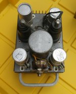
Two 6J7; but doesn't the eBay amp have two transformers and this only has one? 😕
And what you do with a cesium photocell amp these days, I'm not sure. Oh, I know I could wire one in somewhere, and modify it slightly to pass CDs and DACs. But it seems an answer to a question which has been forgotten.
6J7 is a very sweet tube and recently fresh KenRads sold for just a few bucks each. Buy sockets and build something you need in 2021, not 80 years ago.
Attachments
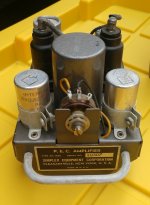
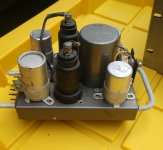
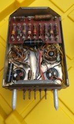
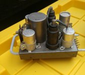
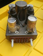
Where on the pictures on Ebay is the second transformer than? I get the impression that the four cans on the four corners are all capacitors so that leaves the bigger can/shield in the middel for one transformer.
Maybe this preamp is useable for electric guitar.
Maybe this preamp is useable for electric guitar.
Attachments
Last edited:
These things were made for movie projector use. Do you have an arc-lamp era 35mm projector?
All good fortune,
Chris
All good fortune,
Chris
Any idea on how I'd go about crafting a power supply for this?
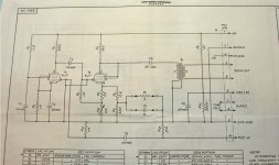
Since as far as I know a photocell draws very little current, B+ has to be about 300 V to reach the 75 V for the photocell on pin 2 of the connector.
So a well filtered power supply of 300 V / 10 mA would do.
...300 V / 10 mA would do.
Yeah. Assuming the "unknowns" (tube drops) are dead-shorts it is 9mA. More likely they are half-way bias, making <5mA.
The input circuit is all wrong for guitar. The 75V DC will not do the pickup and pot any good. There is significant negative feedback making a low input impedance.
The gain from grid to 500Ω winding is about 90. Hot guitar will try to make 0.5V*90 or 45 Volts or essentially +35dBm, which is absurd (there's not +15dBm in here). So it will be all distortion above a light pluck.
Attachments
I take it that by now you also think the schematic I presented in post #5 is the right one?
I missed that R19 of 2M is not grounded so you're right about the feedback.
But for the rest? Why would you connect a guitar to the "PEC +75V" pin? How can you calculate the gain without knowing the feedback factor and transformer ratio? If something takes 300 V / 5 mA, would a 300 V / 10 mA supply not do?
What's next? That I forgot to mention that you also need 6.3 V / 0.6 A for the filaments?
I just tried to help TS. By now he/she must have enough information.
Hello All,
Had to step away from the computer on the weekend to spend some time with my boys 🙂
Original interest here was inspired by a few South Korean builders I'd seen build these into preamps. Sounded like a fun project for couple hundred bucks, though I'm realizing that my technical ability may not be up to snuff.
That being said, cannot thank the group enough here for jumping in and trying to help.
If I've got this right, 300v ~9mA on B+. Then 6.3 V / 0.6 A for the filaments - this is AC not DC correct (for filaments)?
Source input (DAC in my case, no guitar) becomes the "PEC +75V" and output is fed by the 500ohm. What does PEC stand for by the way? And what is the "PEC in" from the schematic vs the "+75" option? Looks like these were the original PS for this preamp.
Thanks again!
Seems like this may work?
Really large for such a small preamp.
As a further answer to your questions - really just doing this for fun as I'm learning and my son loves to get his hands on the soldering iron. It may sound terrible in the end, but we've all gained something from it, time spent together, new learnings, and who knows - maybe a nice piece of gear 🙂
I'm certainly not an electrical engineer and have a long way to go but am so appreciative of the insights and help received from the community here. Took me 2 months to study the last thread I started here and in the end was able to succeed in building what I wanted, so again, thanks for the support...realize I may not ask the right question or be a bit slow on the uptake. Appreciate your continued patience.
My (rethorical) questions were not addressed to you but to PRR. PRR undoubtedly has tons of knowledge and experience, much more than I have. But he also has the annoying habbit of pointing out 'mistakes' which are not mistakes at all. Maybe his eagerness to point out mistakes causes him to not double check before posting. See posts #5 and #6 of this thread and see posts #2, #16 and #34 to #37 of Anything overly bad here? .
Back to topic.
"PEC" stands for "photoelectric cell". These cells were used in movie projectors for reading the sound tracks on movies.
Photoelectric cells need some voltage over them to do their work. The "PEC+75" pin provides that voltage of 75 V. This pin is not for connecting a source like a DAC.
The source should be connected to "PEC.IN." and "SYS.GND.", the last being the ground terminal. But the preamp should be modified a bit before you can use it as a preamp for a DAC. Like the preamp is now, there will be some dc-voltage on the "PEC.IN." terminal (coming from the junction of R6 and R7, through R1 and R19 to "PEC.IN."). The modification also depends on whether the DAC is a 'voltage out' type or a 'current out' type.
As PRR showed, 300 V / 5 mA & 6.3 Vac / 0.6 A will do. If you want the filaments to run on DC you ofcourse need rectification and smoothening of the AC voltage (bridge rectifier-capacitor-resistor-capacitor). For that you need a a bit higher AC voltage and a bit more current so than something like 8 V / 1 A would do fine.
The power supply you linked to is probably for a complete movie projector system so it would be overkill to use it for only one (or two) of these preamps.
Last edited:
- Home
- Amplifiers
- Tubes / Valves
- IPC 1028 Preamp Power Supply Build