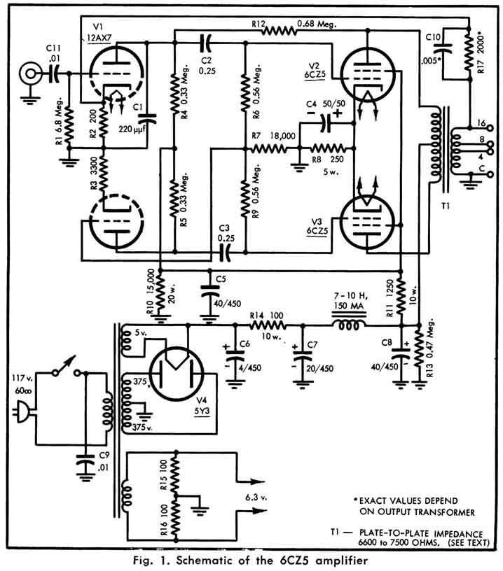
Just found a rather interesting schematic on the audiofanatic website. It appears to use local feedback using one half of the waveform only. The wildly differing resistor values on the splitter cathodes also appear to differ somewhat from the norm.
Anyone care to explain what is going on ??
paul m
Anyone care to explain what is going on ??
paul m
Looks like the first triode is grid-leak biased: the large (6.8M) resistor requires little current (against the tube's grid-cathode diode) from the signal source to bias the tube, as compared to a standard grid leak of say 100k. The voltage developed here makes bias vary wildly but that may or may not be an issue (I'm guessing not). It also reduces or eliminates the cathode bias resistor, which at 200 ohms is probably only there for gNFB. The splitter is paraphase.
Oh, and it also has shunt feedback from the output plate, possibly in an attempt to better balance the paraphase (which is inherently unbalanced by nature!).
Tim
Oh, and it also has shunt feedback from the output plate, possibly in an attempt to better balance the paraphase (which is inherently unbalanced by nature!).
Tim
Sch3mat1c said:. . . The splitter is paraphase.
Oh, and it also has shunt feedback from the output plate, possibly in an attempt to better balance the paraphase (which is inherently unbalanced by nature!).
Tim
Not a bad idea ! I retain it 😉
Yves.
Looks like this was designed "on the cheap". This uses the phase splitter as a voltage preamp as well. Hence, the use of "contact potential" bias, as opposed to straight cathode bias, which would help the balance.
These types of dual tube phase splitters also have the property of having unequal harmonic distortion. Looks like the inner feedback loop is attempting to compensate for that.
Not a bad idea ! I retain it
I would ditch it, in favor of using the 12AX7A as a LTP. That way, you can get rid of the inner feedback loop, and still have a summing junction for the global feedback. Unlike the phase splitter shown here, the LTP doesn't generate harmonic imbalance.
No idea why they didn't do that from the get-go.
It is also better to connect the global feedback loop to the secondary tap you actually use, as opposed to automatically connecting it to the 16 ohm tap even if you're not using 16 ohm speakers.
Yes, this generated an extra few frowns on my forehead too.
V1 anode is really working into a very low impedance. Tube data shows that unless source impedance is quite low, the auto bias arrangement will have quite higher distortion than cathode bias.
Keeping NFB connection at 16 ohm tap may or may not be bad; it depends on the output transformer symmetry. But if the output transformer 4 - 8 ohm "taps" are really taps and not a re-arrangement keeping all the secondary windings in play, h.f. stability will be questionable as well - depending on the amount of feedback.
I suppose it is easy to criticise, but this would not be my choice of circuit either. I do not see that considerations of economy could be so severe that an extra tube could not be afforded in one of the more classic circuits. (And I always had difficulty with high-mu triodes in power amplifiers in terms of bandwidth/feedback stability.) One can further go on about the advantages of distributed load vs. pentode output stages, but you asked for comment on THIS circuit.
Johan
If I'd like to use it as a stereo amp, should i just change the transformer to 6.3V 3A and 375V 150mA?
It doesn't say what it is to start with but obviously, you need twice the ratings for stereo. A 5U4 (or silicon) wouldn't hurt, either.
- Status
- Not open for further replies.
- Home
- Amplifiers
- Tubes / Valves
- Inviting Comment on Schematic