Yeah, you just see those a bit easier with the impedance graph.Sorry made no comparisons by the impedance, just by the already shown nearfield measurements at the port exit. Is it about a possible difference of the losses? I think there is no significant difference
Or in general what's going on in the piston range of the system. 🙂
Nearly identical to the results I got with a square cut pipe without a flare. Only further convinces me the secret sauce is finding the optimum hole geometry that provides sufficient coverage while minimising abrupt edges perpendicular to the duct's internal air flow.Just took a slightly tapered standard reflex tube
@rdf: I mean, the slightly tapering was important to archieve the concentric gap when sleeved with the straight rain gutter pipe 🙂

Standard HP50/180 port from Intertechnik (d = 50mm, l = 180mm). Just flared the inner exit a bit with the help of a hot-air blower and a empty beer bottle, and a round shaped plumbing rubber sealing.

Best regards
Peter
Standard HP50/180 port from Intertechnik (d = 50mm, l = 180mm). Just flared the inner exit a bit with the help of a hot-air blower and a empty beer bottle, and a round shaped plumbing rubber sealing.

Best regards
Peter
you mean printing them with the interior surface upwards? that would probably be better, but it's more wasted support material. the surface needs to be smoothed anyway, so I just took that approach.I would print the ports upright and you won't have all that support material ruining the interior surface.
printing the ports as a whole makes it very difficult to smoothen the interior surface.
great solution, thanks!A bit ago I implemented a pragmatic solution to get rid of the 1st port halfwave resonance by a semi-quaterwave resonator.
the approach is quite similar to the one described in the roozen paper.
covering the absorbers, as you did, to avoid high pressure air chuffing from the box inside to the port is essential - I am not sure that was included in the roozen paper.
exaclty!Only further convinces me the secret sauce is finding the optimum hole geometry that provides sufficient coverage while minimising abrupt edges perpendicular to the duct's internal air flow.
I used perpendicular tubular absorbers half filled with melamine foam (deriving from my idea of tuned quarter-wave-absorbers).
as far as i experienced it is enough to have just one hole to dampen the resonance.
further experiments will follow!
you are right, I can still print them in two halves. Thanks!upright with exit/entrance on the bed.
chuffing excitation measured in 1 dB steps
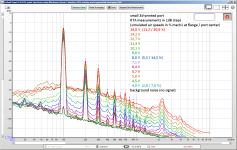
a general conclusion:
I scaled the previous 3d printed port down for the small 3d-print, not fully considering that the roundover radius of the flanges should not be scaled, because the beginning of turbulent flow is only dependent on air speed and roundover radius, not the port dimensions.
thus the chuffing/blowing starts quite early.
some observations, however:
- the 2,2 kHz longitudinal resonance is being strongly excited between 5,7 and 7,1 V and rises constantly after that. no resonance below 5 V.
- the low frequency turbulent airflow noise is strongly excited between 7,1 and 8 V. it rises further but remains quite stable above 12,7 V.
- chuffing seems "acceptable" below 6,4 V, at least with the constant sine tone I listened to. the relevant parameters here would be the flange airspeed of about 5% mach 1 and the flange roundover of 6,5 mm.
I suppose the low frequency turbulent noise could be reduced with a larger roundover.
the high air speed at the port center seems to be OK, according to the smooth/rough surface test. turbulences at the surface of the port center would add high frequency noise.
ADDENDUM:
I simulate the air speeds with hornresp, by changing port surface and length to match the tuning and the existing cross section of interest of the sloped port.
thus, it's just a very rough estimation!
Last edited:
Understood, thought about a sleeve but never tried. You also got equivalent results within the bandwidth displayed with much fewer holes.sleeved
here is the solution combining resonance absorbers and still no chuffing, using the big 3d-printed port:
until now this is the best performing port combining good (low) resonance and still good chuffing behaviour, not degraded by the resonance absorber.the only difficulty may be the life expectancy... but that will be solved!
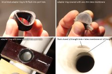
the air pump absorber, previously causing some turbulent airflow at the highes air speed section, is decoupled with a very thin elastic membrane.
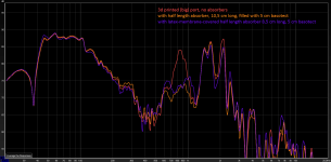
the added weight of the membrane needed a slight reduction of absorber lenght and reduced the efficiency slightly. thus, I may need additional or bigger openings. which, of course is no problem anymore, because they can be covered to avoid turbulences.
I might even call the membrane a turbulence preservative 🙂.
the response, compared to no absorber and the absorber without latex membrane:
the best part is the chuffing graph (in shades: 1 V - 2 V - 4 V - 8 V - 16 V):
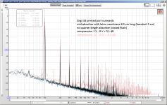
no chuffing up to 8 V. even 16 V (central air speed ~10% of mach 1) is not that bad!
(edit: not even sure if the chuffing noise is caused by the absorbers - it might just be the flange roundover turbulence)
compare it to the open absorber version.
of course also the 1/4 length absorber can be equipped with the same membrane.
kudos (once more) to @augerpro who did something similar with a heavier rubber cover for multiple port holes.
Last edited:
Nice Idea - KHF implemented a similar design to the new Epos ES14N :
https://epos-loudspeakers.com/products/es14n/
--> Tab "Cabinet"
"In order to compensate for the open tube resonance of the port, some openings were added in the middle of the port. To avoid loss of low bottom end, those openings are covered with soft material, tuned to only kill the unwanted resonances of the port."
I will test it! However it will only be useful for a port outside the reflex chamber (see below).just have those holes covered with latex but no chamber on them
Thanks for directing me to this speaker!some openings were added in the middle of the port
I don't fully understand the concept of opening the resonance absorbers to the bass reflex box interior, if i interpret the drawing correctly.
Of course that would create losses and severe chuffing through the holes, which should be avoided.
The pressure in a bass reflex chamber gets very high at helmholtz resonance, the pressure in the middle of the port however is quite low (high speed, low pressure).
(Edit: port resonance however has a pressure maximum at the port center. But it's small compared to the bass reflex pressure in the enclosure.)
Of course the pressure will try to escape through the holes in the port.
Closing them with a material to withstand the bass pressure and thus reducing the resonance absorption defeats the whole concept, as far as I can see.
I think this concept was very shortly described in the roozen (philips) paper, if i read it correctly.
They show the port directed to the (normal atmospheric pressure) outside, which is ok, of course. But they did not mention the importance of that fact.
But the again, who am I to question scientific reports 🙂.
Last edited:
That's why an acoustic band-stop filter has a closed volume;The pressure in a bass reflex chamber gets very high at helmholtz resonance, the pressure in the middle of the port however is quite low (high speed, low pressure).
(Edit: port resonance however has a pressure maximum at the port center. But it's small compared to the bass reflex pressure in the enclosure.)
Of course the pressure will try to escape through the holes in the port.
Closing them with a material to withstand the bass pressure and thus reducing the resonance absorption defeats the whole concept, as far as I can see.
https://en.wikibooks.org/wiki/Acoustics/Filter_Design_and_Implementation#Band-stop_filter
That way you keep the pressure inside the entire system.
I also still have my doubts from the theory of acoustics I know and I have learned, that just some holes are gonna have a satisfying result for exactly this reason.
Or it will only work when the BR-port is inside the cabinet. (since than the pressure is equal)
Anyhow, it does always add an additional unknown variable aka it's less predictable.
Btw, I had this idea with holes around the tube with an additional tube around it many years ago as well 🙂
This is what they basically use in car mufflers.
The idea just never came to actual practical tests (for no particular reason aka life just happened).
It's just very interesting how people have the same idea, but even more interesting why it's not been done much.
Somebody who reads well and thinks critical?But the again, who am I to question scientific reports 🙂.
I have seen and read many many many reports over the years, also from interns I was/am coaching.
Some are great, some totally miss the point, some miss an entire VERY important step meaning that the entire findings are wrong (this is particularly a thing with FEM/BEM research projects).
The fact that something is a "scientific report" doesn't give it a holy status.
The whole point is the have discussions and dialogue.
You always have to on your guard with "papers" from known brands.
Not about what they tell, but mostly about the stuff they leave out (and why).
By the way: thanks for your perfect implementation, the measurement result is very convincing!Starting from this:
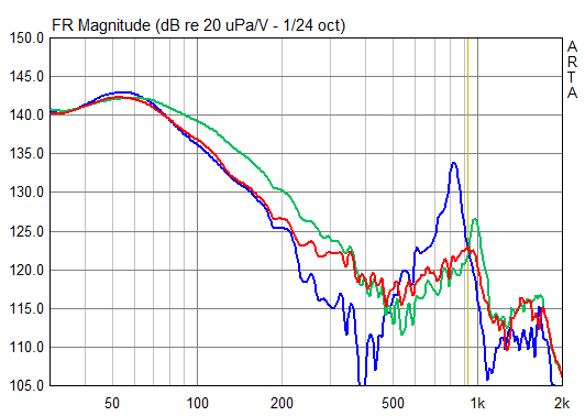
(EDIT: blue = original without measures, green = just boreholes middle of tube, red = boreholes wrapped with damping material)
I suppose due to the nearly constant wide cross section of the port the airspeeds are low and (port perforation) chuffing is not that noticeable, am I right?
I nearly decided that I'll just quit using ports, because after studying them in depht they seemed to be so flawed ...The idea just never came to actual practical tests
Like anything else in physics? 😉they seemed to be so flawed .
Pick your compromise, there is no best and no free lunch.
A lot of problems are already less severe in a 3-way or FAST system.
Unfortunately we will get a bunch of new ones.
We can never win.
- Home
- Loudspeakers
- Multi-Way
- Investigating port resonance absorbers and port geometries