Of course - yes, I agree.lower Q factor
I still had chuffing and turbulences in mind!
as @b_force mentioned some days back, Q factor can be measured via impedance. I wanted to investigate how my 3d-printed port, the "flat port" and the small port compare and wether the absorbers have a big influence.
the small port was too short and had to be extended slightly from 72 mm to 85 mm. now all ports seemed to match tuning quite closely.
here are the impedance curves.
note that the ports have been directed to the outside, thus the tuning of chamber 1 was slightly lower than my previous impedance graphs because of additional volume, so I only compare the curves against eachother:
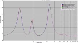
and zoomed in for detail between 40 and 200 Hz:
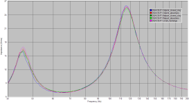
while there are some slight differences they seem to be within measurement tolerances.
the small port with "best" lenght/diameter ratio has the highes peak at 45 Hz.
the flat port has marginally lower peaks than the 3d-printed port.
drawings of different ports in post #157.
a small 3d-printed port is just being manufactured.
I will also try a small very flat port to measure the impedance and see if it reduces Q factor.
the small port was too short and had to be extended slightly from 72 mm to 85 mm. now all ports seemed to match tuning quite closely.
here are the impedance curves.
note that the ports have been directed to the outside, thus the tuning of chamber 1 was slightly lower than my previous impedance graphs because of additional volume, so I only compare the curves against eachother:

and zoomed in for detail between 40 and 200 Hz:

while there are some slight differences they seem to be within measurement tolerances.
the small port with "best" lenght/diameter ratio has the highes peak at 45 Hz.
the flat port has marginally lower peaks than the 3d-printed port.
drawings of different ports in post #157.
a small 3d-printed port is just being manufactured.
I will also try a small very flat port to measure the impedance and see if it reduces Q factor.
Classic! lol, that brings back memories!And, yes 😳 Impedance measurement still done in speaker workshop ...
I am surprised you even got it working at all with measuring stuff.
If you can go lower to like 22kHz, that would be nice to get a bit more frequency resolution.
As well as taking a bunch of averages (that goes with a log, so don't do more than like 8 or 16, otherwise you're waiting forever)
Thanks for that suggestion, will try it out today!If you can go lower to like 22kHz
I still happily use a prehistoric dell laptop, almost 15 years old and still running with windows xp and a focusrite 4/6-channel interface connected via firewire.
I'm happy REW (and sw, of course) works flawlessly on that computer.
As far as i know speaker workshop has been ported to windows7 (not sure if it works on newer versions), if you ever wanted to use it again!
No thanks, I will keep it at nostalgic memories 😀 😀 😀if you ever wanted to use it again!
small 3d printed port
small port corresponding to the tiny cardboard tube with 2,5 cm diameter (see post #157), but avoiding the turbulent airflow starting at low levels (#165).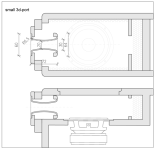
I tried to produce a perfectly smooth surface by sanding, filling, sanding, painting ...
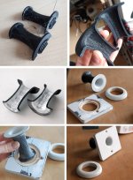
response, together with the original 72 mm cardboard tube and the extended version (84 mm) that corresponds to the tuning of all other ports. tested and verified with impedance measurement.
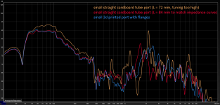
(i will investigate the bass output differences during the next days!)
for comparison, here is the response of the small 72 mm port compared to the big ports (length 205 mm):
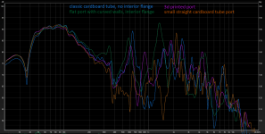
the small opening surface surely reduces all resonances. furthermore the short port has a much higher port length resonance (around 2,2 kHz).
now the chuffing results at 100 Hz (1 V - 2 V - 4 V - 8 V in shades of grey):
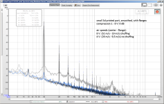
up to 4 V there are no signs of chuffing!
at 8 V input there is a general turbulence noise and a peak at the lenght resonance. the air speed is VERY high, of course.
the wideband noise at high level is created by the "port stalling", the blowing effect can be detected from half a meter distance.
while a noise floor at high music level might not be bad, this one is modulated by bass frequency and is very audible.
the small port resonance peak was not even that recognisable.
I think the small ports (cardboard and 3d-print) demonstrate very clearly that a good port shape and a smooth surface allow very small port dimensions:
- enclosure resonances are attenuated
- port resonances are reduced (better relation between diameter and lenght) and higher up in frequency
- chuffing can still be controlled by chosing the right port shape and surface
I will investigate further ...
Last edited:
while testing the small 3d-printed port I made another discovery:
when mounting the port directed to the outside there is no (or just a tiiny little) port lenth chuffing resonance:
(1 V - 2 V- 4 V - 8 V in shades of grey)
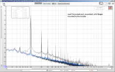
my explanation:
when the cone moves and compresses the air inside the enclosure the air moves (except, of course at the enclosure walls). this air movement induces turbulences at/along the port edge (similar again to a pan flute) and this excites the longitudinal resonance.
when mounting the port directed to the outside there is no (or just a tiiny little) port lenth chuffing resonance:
(1 V - 2 V- 4 V - 8 V in shades of grey)

my explanation:
when the cone moves and compresses the air inside the enclosure the air moves (except, of course at the enclosure walls). this air movement induces turbulences at/along the port edge (similar again to a pan flute) and this excites the longitudinal resonance.
influence of smooth/rough surfaces
here is a quick test regarding surface smoothness that I did by simply gluing sand to get a rough surface at different sections of the port.I used masking liquid as glue that can easily be removed again.
I should mention that for the smooth surface of the port as tested also in the previous posts I followed these steps:
- first evening out of (my rather rough) 3d print half-shells with 60 grit sanding paper. this is mainly just to remove printing artefacts and burrs.
- apply filler/putty on all interior surfaces to fill layer gaps
- sanding with 120 grit paper
- eventual additional filler for remaining holes
- sanding with 180 grit paper
- applying one or two thick coats of primer, trying to get an even surface.
- sanding with 360 paper and finally with 1500 grit fleece
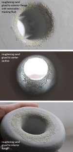
measurement with 8 V input:
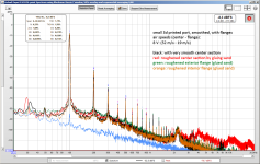
as to be expected the central section is heavily affected due to high air speeds (red curve). added noise from 2 kHz up, very audible!
lower air speed flanges are not that much influenced by rough surface. the exterior flange has some added noise in the lower spectrum (this is the turbulent air flow due to port stalling).
the interior flange remains quite similar, with just very little added noise above 2 kHz. the noise is mostly absorbed by the box interior.
i will do another test with roughened exterior flange with lower power, when there is still no turbulent airflow.
I have almost completed my on an off pondering and am now thinking about implementing some software suitable for simulating the details about the sound in and around ports. It will likely take a few weeks if things go smoothly (it almost never has in the past and the exercise is also being used to learn about some software that is new to me). Are you happy and able to provide the geometry, related information (e.g. driver, damping material,...) and measurements for some of your test cases?
That's great!Are you happy and able to provide the geometry, related information (e.g. driver, damping material,...
I can give you everything I have.
I'll post a pdf including everything, if that's ok for you.
I fogot to mention one important step, here it is:
- gluing the half shells together. The following steps are easy with the small port. The interior of the big 3d-printed port is not accessible by hand, so the gluing of the shells comes last.first evening out of (my rather rough) 3d print half-shells with 60 grit sanding paper. this is mainly just to remove printing artefacts and burrs.
- apply filler/putty on all interior surfaces to fill layer gaps
- sanding with 120 grit paper
- eventual additional filler for remaining holes
- sanding with 180 grit paper
- applying one or two thick coats of primer, trying to get an even surface.
- sanding with 360 paper and finally with 1500 grit fleece
I can give you everything I have.
I'll post a pdf including everything, if that's ok for you.
Thanks that would be useful. Do you have solid models in some form for your geometries? What format are your measurements stored in?
The enclosure and the simple geometry ports are drawn in 2d (dwg). I can easily provide a 3d model in your desired format.Do you have solid models in some form for your geometries?
The 3d printed ports are drawn in fusion360, i can export any useful 3d format.
The response graphs are done in REW, the collections are in mdat file format. I can export response curves (frd) or impuls responses (wav).What format are your measurements stored in?
The chuffing noise measurements are simple screenshots of REW real time analyzer window.
Let me know what formats you can use!
(By the way, I joined diyaudio just 9 days after you!)
Last edited:
Hi all,
nice research, thanks for sharing!
A bit ago I implemented a pragmatic solution to get rid of the 1st port halfwave resonance by a semi-quaterwave resonator.
Starting from this:
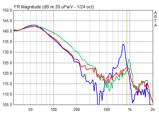
(EDIT: blue = original without measures, green = just boreholes middle of tube, red = boreholes wrapped with damping material)
I came to this:
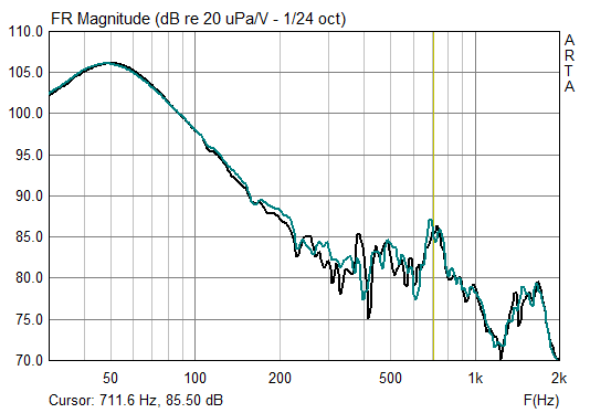
With the following setup:
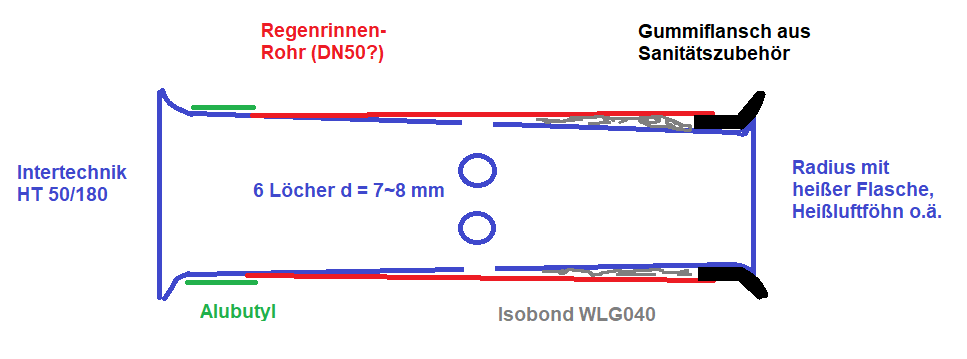
(German, sorry. But I think you get the idea....)
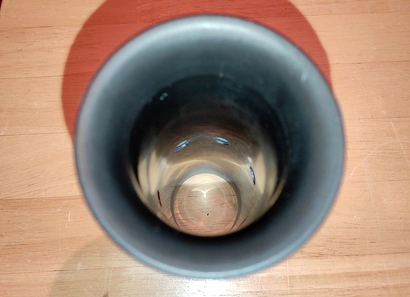
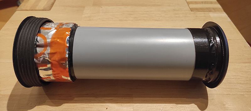
Just took a slightly tapered standard reflex tube, and put a rain gutter pipe slided over it concentrical, sealed by a rubber ring on the open end. 6 Boreholes at 1/2 length with rougly the area of the concentric slot. Slot length became roughly 1/2 length of the reflex tube, and very lighty stuffed with damping material.
For the given efford I'm very happy with the result 🙂
Best regards
Peter
nice research, thanks for sharing!
A bit ago I implemented a pragmatic solution to get rid of the 1st port halfwave resonance by a semi-quaterwave resonator.
Starting from this:
(EDIT: blue = original without measures, green = just boreholes middle of tube, red = boreholes wrapped with damping material)
I came to this:
With the following setup:
(German, sorry. But I think you get the idea....)
Just took a slightly tapered standard reflex tube, and put a rain gutter pipe slided over it concentrical, sealed by a rubber ring on the open end. 6 Boreholes at 1/2 length with rougly the area of the concentric slot. Slot length became roughly 1/2 length of the reflex tube, and very lighty stuffed with damping material.
For the given efford I'm very happy with the result 🙂
Best regards
Peter
Last edited:
The enclosure and the simple geometry ports are drawn in 2d (dwg). I can easily provide a 3d model in your desired format.
The 3d printed ports are drawn in fusion360, i can export any useful 3d format.
STEP files exported from fusion360 should be useful (fusion360 is not available on linux). 2D drawings with dimensions on should be fine for everything without a 3D model.
The response graphs are done in REW, the collections are in mdat file format. I can export response curves (frd) or impuls responses (wav).
I have REW installed and can work with mdat files.
The chuffing noise measurements are simple screenshots of REW real time analyzer window.
Screenshots require tracing which it would be good to avoid if possible. If the measurement data is stored in raw format using that should be fine (and a bit more reliable since it hasn't always been clear to me quite what processing REW has applied).
I am going to be moving fairly slowly at this end so no immediate need for anything.
@b_force: Sorry made no comparisons by the impedance, just by the already shown nearfield measurements at the port exit. Is it about a possible difference of the losses? I think there is no significant difference. Within the first plot you can see that I got rid of the resonance quiet well with just the holes + wrapped damping foam, but lost a dB or so at the tuning frequency. This is avoided now with the concentric tube. Subjectively there is also no difference with chuffing, Measured SPL limit of the little speaker (SB15NBAC30-4 with extra magnet in ~8,5 litre) is ~94-95 dB @ 1m before and after the modification, due to suddenly woofer offset jumping caused by the port nonlinearity when turbulence sets in.
With the following setup:

(German, sorry. But I think you get the idea....)
This looks close to the linings in aeroengines for noise reduction. Should be effective if the tuning is appropriate.
- Home
- Loudspeakers
- Multi-Way
- Investigating port resonance absorbers and port geometries