back to the main topic: port resonance absorbers!
after a disappointing and discouraging result of a small helmholtz port resonance absorber (tiny plywood box filled with polyester batting, see post #58) I took some time off and then investigated the influence of an adjustable empty pipe resonator mounted to the port, see post #167.the breakthrough however resulted from partially filling the resonator pipes with open cell melamine foam (basotect) cut to fit the resonator tube.
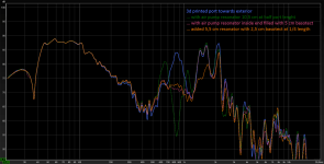
here is an overview of optimization process:
- blue: no absorbers (only the 3d printed port)
- green: absorber with 10,5 cm lenght at half port lenght. the absorber tuned to the port lenght resonance does actually work, but it creates peaks above and below the absorbed frequency.
- red: same absorber, but the interior part of the absorber is filled with 5,5 cm basotect.
- orange: added a second absorber (syringe) at 1/4 lenght of the port, the outside part. this absorber has ~5,5 cm lenght and is filled with 2,5 cm basotect.
keep in mind:
pipe open at both sides has a first longitudinal resonance at frequency with wavelenght double the pipe length (the port).
pipe with one closed end (absorbers) resonates with wavelenght = 4*pipe length.
for best efficiency the resonators need to be located at the pressure nodes and have half of the open pipe length.
I also tried to vary the resonator lenght including the basotect dampening. the optimum lenght was still as described above.
optimum basotect filling in my case was determined by testing:
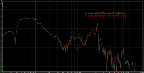
(edit: corrected description in the image)
basotect seems to work best here because it does not (or just barely) vibrate and thus will not absorb bass energy.
stay tuned for chuffing tests with these absorbers!
Last edited:
Great multiple pun, especially the stay tuned part 😀 😀 😀stay tuned for chuffing tests with these absorbers!
the stay tuned part
thanks guys for the encouraging resonance! 😊Blockbuster
chuffing of 3d printed port with absorbers
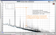
here is the chuffing measurement of the 3d printed port with both absorbers and basotect filling (orange response graph in message #202);overlay of 1 V - 2 V - 4 V - 8 V spectrums in shades of grey:
for comparison the 3d printed port without absorbers (same as in message #161, port directed towards the interior):
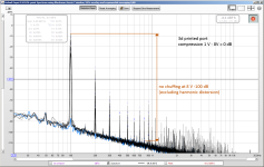
as stated before: disregard the absolute measurement differences due to slightly modified parameters.
it is clearly visible that the rather sharp 2 cm absorber hole at the central high speed air section creates some turbulence, but only with the highest 8 V input. I will have to investigate further to optimize this section, eventually also widening the absorber "entrance" to slow the air speed and make the absorbtion more efficient and eventually increase the absorption frequency bandwidth.
note that the turbulence noise has no resonance peak at all, so will be less noticeable / less annoying.
the absorber probably eats up the resonance peak and furthermore I suspect that turbulences inside the port will not excite resonances as much as turbulences at the ends/edges, like a pan flute:
Did your ear agree with the measurements? I found it wasn't so easy to identify in the distortion plots when chuffing was audible, but I clearly heard when it started and got worse. I also noticed that it was not really correlated with the harmonic distortion "forest" that grew with level, but a broadband noise from 1-2khz that most correlated with what I heard. I think I see it in your first plot if I understand it correctly.
Looks like we are on the same wavelength. 😉thanks guys for the encouraging resonance! 😊
I must apologize for the slightly misleading table in post #162. while this table is correct for max. air speeds, these air speeds are for 50 Hz, not 100 Hz as I was testing for chuffing. so the airspeed numbers in the chuffing graphs are all about 30 % too high.
sorry for that - I will try to have the images corrected or have a remark regarding this!
here is the correct air speeds table related to the chuffing tests at 100 Hz, valid for all curved wall ports (air speeds as simulated in hornresp):
I will also repeat some chuffing tests with 50 Hz and resulting higher air speeds and greater air movement.
the general results until now shoul still be valid, however!
sorry for that - I will try to have the images corrected or have a remark regarding this!
here is the correct air speeds table related to the chuffing tests at 100 Hz, valid for all curved wall ports (air speeds as simulated in hornresp):
| Input voltage | Port speed (narrow center) | % of C | Port speed (both ends) | % of C |
| 1 V | 2,0 m/s | 0,6 % | 0,8 m/s | 0,2 % |
| 2 V | 3,9 m/s | 1,1 % | 1,5 m/s | 0,4 % |
| 4 V | 7,9 m/s | 2,3 % | 3,1 m/s | 0,9 % |
| 8 V | 15,8 m/s | 4,6 % | 6,1 m/s | 1,8 % |
I will also repeat some chuffing tests with 50 Hz and resulting higher air speeds and greater air movement.
the general results until now shoul still be valid, however!
Did your ear agree with the measurements?
Thanks for your suggestion - while doing listening tests I discovered my airspeed mixup (see previous post)!
So I just did a listening test with the port output about 50 cm from my head.
the 3d printed port with both absorbers at 100 Hz and 8 V rms input just started to make some barely audible noise, so this seems to follow the measurement.
however, the noise audibility depends very much on the sensibility of hearing at the fundamental frequency, so it will be considerably worse with lower frequencies:
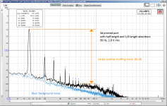
with 50 Hz the air speed is 30% higher and human hearing much less sensitive, thus the noise started to be audible already at 2,9 V.
Here is the corresponding graph:
thanks a lot tenson!Great work STV! Do you have an end goal and project for this port?
my interest in port resonances started when during the pandemic and after nearly 20 years I finally started working again on a set of two-way-speakers that I never completed. these boxes have (or had) some severe flaws:
- tweeter mounted centrally and even with the same distance to the top baffle edge
- air leaks around the woofer basket
- similar height and depth of the enclosure
- quite resonant and too large 5 cm diameter bass reflex port mounted on the front baffle
this is how the NF-response of the midwoofer looked like, with open and stuffed port:
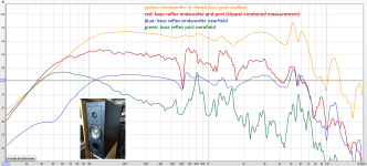
lots of bad resonances and cancellations between 550 and 2000 Hz!
I will install new optimized ports on the back, a new baffle with CNC-cut waveguide, optimized crossover, oak veneers on the sides ... it's a project to try out all sorts of nice things.
I also plan to build a soundbar for my girlfriend's workshop. I have some challenging ideas with a cardioid MEH plus vented woofers next to the back wall for bass reinforcement. I should add I have a very patient girlfriend!
besides these specific projects I quite enjoy the investigative research work.
Can you expand on this, why would a port be too large?too large 5 cm diameter bass reflex
I use a 10 cm port in a 10-inch two-way speaker, mounted on the back.
It's (as always) a tradeoff and a compromise.Can you expand on this, why would a port be too large?
for my specific case these are my considerations:
- the woofer is very small (4") and has quite low Xmax (2 mm). the maximum displacement is small, thus the air passing through the port is also small and the max airspeed will not be high.
- transmission of enclosure resonances is depending on the cross section of the port. ports with more surface transmit more enclosure resonances.
- port resonances depend on port length. best would be to keep the port resonances out of the midwoofer passband (not entirely possible for most 2-way systems).
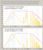
I made a quick simulation with hornresp, using the offset driver/offset port model, trying to replicate my existing box.
the upper graph represents the existing enclosure with 5 cm port.
lower graph is just an example with 3 cm port. this is probably too small, as the airspeed is getting quite high already. but it shows the resulting much reduced port resonances and reduced enclosure resonance transmission (have a look at the 525 and 1050 Hz peaks).
for a woofer in a 3-way system, a WAW, or a subwoofer where port and enclosure resonances are far out of the usable passband it makes sense to use the biggest possible port to avoid chuffing and compression.
it's also much better (as you did) to direct the port to the back of the speaker, because this reduces audibility of higher frequency resonances due to directivity.
Also, short and wide ports will not resonate as much as long thin ones. small low VAS woofers usually need very long (strongly resonating) ports.
I suppose a 10 cm port is just right for a 10 inch driver!
Last edited:
Addendum:
I just realized smaller ports have a smaller length/diameter ratio.
They are thus less prone to resonances, as far as i understand.
I just realized smaller ports have a smaller length/diameter ratio.
They are thus less prone to resonances, as far as i understand.
Thx for explaining your reasons.
I don’t enjoy the amount of resonances with my solution.
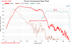
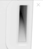
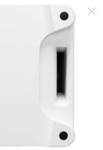
I was also quite surprised to see what Genelec achieved with their slot ports (with their somewhat modified oem version of the woofer I use):
How does the calculation for a rectangular port change the matter: is the resonance escaping along the width, or the height?
I don’t enjoy the amount of resonances with my solution.
I was also quite surprised to see what Genelec achieved with their slot ports (with their somewhat modified oem version of the woofer I use):


How does the calculation for a rectangular port change the matter: is the resonance escaping along the width, or the height?
along the length! 😊is the resonance escaping along the width, or the height?
the port resonates along it's length.
it furthermore will transmit enclosure resonances, according to it's response curve.
see post #157 showing my "flat wide port" (127 / 56,9 mm wide and 14,2 mm high) with response graph and #165 with chuffing measurements.
my response is probably influenced by the fact that the wide port nearly touches the side walls of my box and transmits more enclosure width resoances.
a flat port behaves very well, as far as I have experienced.
What do you mean with this?a flat port behaves very well, as far as I have experienced.
A flat port has a lot more issues with the boundary layer effect.
Resulting in more resistance, therefore Q factor of port goes down.
This can be easily measured and seen with an impedance measurement.
My experience is that a slot port (flat port) can be very tricky and most certainly doesn't behave textbook wise because of the things I just mentioned.
Obviously all compared to the same Sd to like a good round port.
Because of the length/width ratio, they have a tendency to do a bit better in terms of port resonances (aka standing wave)
That is most probably true, as the surface is bigger.A flat port has a lot more issues with the boundary layer effect.
However as I saw and heard during my experinents the main issue is the port openings inside and outside.
So in my opinion (until now - I may still change it ... my search for the best port is still ongoing*) there will be severe turbulences at the mouth/throat due to air flow separation of oscillating air (this is very different from any constant fluid flow) long before the boundary layer issues will arise.
*I am doing my tests with a small woofer and a small port, scaling may also introduce changes.
Even at very low voltage levels, the lower Q factor can be measured and seen in the impedance curve.there will be severe turbulences at the mouth/throat due to air flow separation of oscillating air (this is very different from any constant fluid flow) long before the boundary layer issues will arise.
At these levels there won't be any turbulence yet.
In practice many people do pick a slot port with a much bigger Sd compared to a round port.
Mostly because they like to have the same width as the diameter of the woofer or cabinet.
- Home
- Loudspeakers
- Multi-Way
- Investigating port resonance absorbers and port geometries