Rüdiger,
your statements regarding bandwidth and some other things are very confusing. To me, the FC is nearly worthless, a particularly ineffective linearizing mechanism. One way to increase the bandwidth would be reducing the extremely harmful Miller capacitance you are looking for. The FC will do nothing about it at all. It is useless.
your statements regarding bandwidth and some other things are very confusing. To me, the FC is nearly worthless, a particularly ineffective linearizing mechanism. One way to increase the bandwidth would be reducing the extremely harmful Miller capacitance you are looking for. The FC will do nothing about it at all. It is useless.
Rüdiger,
What is the impedance of your headphones?
Not very accurately.Lumba, did you read my posts?
What is the impedance of your headphones?
Hi,
my headphones are Sennheiser HD560, I guess they have 300R impedance. I ran both sides together, so it goes down to 150R.
Note I don't think it really qualifies as an headphone amp, a square wave gets nasty overshoot spikes. The sound is amazingly good, though.
The gain goes down from ~40dB to 28dB.
Anyway, I am most surprised that you think a folded cascode does not work like a cascode regarding linearizing the cascoded device.
To me, a cascode qualifies as one, when current- and voltage swing are divided up in two devices, in the way that the cascoded device provides current gain and the upper device performs the corresponding voltage swing.
The mixed mode I use here is not my invention, it has been used by John Curl, Nelson Pass (in the A75) and Erno Borbely (in his last articles).
Rüdiger
Rüdiger,
the only thing I like in your design is the lack of global NFB. Maybe you should forget about it and concentrate on the other one. Start matching at the intended Vds bias (4-5V) using about 150 Ohm source resistance.
Disturbingly, you are often referring to simulation data having no relevance to the sound. I do not give a dime for those.
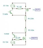
300 Ohm impedance is favourable from a practical viewpoint. A suitable output stage could be:
the only thing I like in your design is the lack of global NFB. Maybe you should forget about it and concentrate on the other one. Start matching at the intended Vds bias (4-5V) using about 150 Ohm source resistance.
Disturbingly, you are often referring to simulation data having no relevance to the sound. I do not give a dime for those.
300 Ohm impedance is favourable from a practical viewpoint. A suitable output stage could be:
Attachments
Hi Lumba,
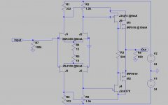
*Which* data is only simmed? Anything presented here is confirmed by acutally building the circuit, and sim is pretty close to measurement (which is limited, because I only have a scope and a sig-gen).
I even listened to it using the circuit as an headphone amp. For clarity I'll post that version here.
You say FC is worse in linearizing the input devices, but you don't say *why*. It would be great if you do.
From all I read, your assumption that FC does nothing against miller must be wrong.
With R1/R8=0, Miller would be completly absent without cascode. Of course, deltaV against deltaI would be still a problem.
Why do you think I need source degeneration in the output?
Rüdiger
Attachments
Hi Rüdiger,
the purpose of cascoding is to improve linearity, bandwidth, gain, noise, load impedance, ripple rejection, to provide insulation and to prevent thermal related distortions in those highly sensitive chips. Nothing of that is achieved with the FC arrangement. Vds must be kept small and firmly locked by applying a stable, low impedance reference voltage to the drain and source terminals. Not using any source resistors is very unwise.
The CFP has an inherent powerful linearizing mechanism, much more powerful than folded cascodes, NFB or dubious, complex and deteriorating error correction circuits. It can use up to 100% voltage feedback, working in an effective, direct and precise manner without any additional parts whatsoever, thus allowing a clean and straightforward signal processing. For its operation and stability, speed is essential. Therefore, regarding the output stage, lateral MOSFETs and high voltage, fast bipolars with very low Cob as drivers (from Sanyo or Toshiba) are the best choices. As the drivers being referenced to the output, the output impedance is low. Please note, those resistors are not in the source line.
Avoiding NFB gives important sonic advantages and can be done successfully, but not easily. Considerably more attention to the details needs to be paid.
Hi Lumba,
I re-read some of the stuff related to folded cascodes and tried some things. It seems to me now that you raised valid points. Even if a folded cascode *does* fix the voltage of the cascoded device, the remaining bit seems distorted, which is not the case with conventional cascode, for instance. The fc is not famous for very low distortion...
The fc still has appeal, since it overtakes two functions in a single device: cascoding and VAS, even if flawed compared to more-stage solutions. Linearizing the FC-Q makes things a bit better.
The discussed circuit here should be used as a second gain stage in a phono amp, so I will try other solutions as well. Especially the cfp-input-pair-threads draw my attention.
thanks,
Rüdiger
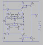
Once again, I stumbled over the UGS-thread and I thought that it may be a good starting point for my purpose.
Below is a first sketch.
Gain might be a bit high (around 59dB), and although I followed the instructions posted in diyaudio sometime ago, I couldn't persuade LTSpice to compute distortion numbers for that (or any other) circuit. It might not be too useful if I could, anyway.
I will build it and report.
Any advice or comment would be welcome, even if negative (I'm used to it).
Rüdiger
Attachments
- Status
- Not open for further replies.
- Home
- Amplifiers
- Solid State
- Inverting FET openloop gainstage