Well im afraid i already know the answer. but it never hurts to ask maybe someone has a great idea, could i convert a inverted esl to a stacked innverted esl?
so the audio signal remains on the foil, and one extra stator and foil is added. but to keep the foils in sync the audio have to be reversed on the second foil...
now in a inverted version one side of the trannie is connected to ground from the voltage multipliers. and one is not. the one that is connected to the voltage multipliers should be conencted to the next membrane and visa versa if this thing was able to work. but i see some problems there 🙁 im afraid i end up needing 2 trannies to accomplish this.. and that kind of beats the purpose. since adding 1 stack equals +5-6dB adding twice the stepup ratio will result in the same...
any one has a better idea ? can i isolate the audio from the stepup circuit somehow? so i can still be able to feed it to the foil without losing output ?
another option is use the center tap to connect to the high voltage and use the other end of the trannie for the next foil. but that results actually almsot the same output as a normal ESL i guess with the same tannie.. 🙁 damned.
what does work of course is like flipping a panel behind the excising one. but its it not at all charming and must have some sort of isolation between +3000volt dc constant and -3000volt... might be a bit prone to failure and hard to keep thin
Last edited:
What seems to be a problem? AC signal goes through the multiplier's capacitors. Capacitance the signal is fed through has to be higher in value than the stator to diaphragm one, at least 10 times or so. You also may use separate set of two caps connected to stators with common point connected to the secondary of audio tranny as per drawing of yours. Please use proper rated (voltage vise) caps.
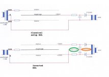
yeah thats just a plain inverted esl. as seen on the video that is playing. i wondered if i could pull the same trick as i did with normal esl's. stator mylar stator mylar stator. in the normal version you just reverse the bias on the mylar for one membrane so the backstator becomes the front stator for the next membrane.
Now i wanted to see if i could do the same with an inverted esl. it would make the speaker another 6 db more efficient and it might be possible to scale things down.
Now i wanted to see if i could do the same with an inverted esl. it would make the speaker another 6 db more efficient and it might be possible to scale things down.
This page has theoretical discussions similar to those you seem to be pursuing. No practical examples though. Whether constant charge operation can be maintained in an inverted ESL still seems questioned also.
If noting else, the referenced patents might point you to some useful ideas.
https://www.tubecad.com/2010/01/blog0179.htm
If noting else, the referenced patents might point you to some useful ideas.
https://www.tubecad.com/2010/01/blog0179.htm
This page has theoretical discussions similar to those you seem to be pursuing. No practical examples though. Whether constant charge operation can be maintained in an inverted ESL still seems questioned also.
If noting else, the referenced patents might point you to some useful ideas.
SuperTriodes & Inverted ES Speakers
i am afraid it wont 🙁 the inverted ESL work. no problem. the thing i ask is kind of different.
this it what i meant
sandwich esl ?Yummie
but then withn using inverted
So im having a weird thing. if i follow the schematic one on one and i use 10Mohm resistors for all resistors and 0.047uF capacitors, i get hardly any sound.
when i remove the resistor at the green circle (attached image) i get sound. another weird thing. if i use 4 caps in series instead of normal 2 to increase voltage rating. i get more output. but ofcourse it did cut the 0.047 into 2. so lower works apparently better for me... but why and why does it not work with the resistor on the audio signal not going to the panel ?
also in this image it looks like they used a transformer for the high voltage with a 0 lead ? in my design the 2 cascades are fed by an inverter for cold cathode tubes. i have this wire (orange circle) connected to the beginning of the first stage of the multiplier, where it is still AC
Attachments
Last edited:
That inverted circuit you posted is from the Final Whitepaper and is incorrect, incomplete, or may intentionally miss-leading as shown. The green resistor you circled should not be there or should at most be 100K or so. The other two resistors should be 10Mohm, but should be on the other side of the 0.047uF capacitors. Attached is image from their patent which should hopefully make more sense.
As you properly reasoned, a stacked inverted ESL would require an additional transformer.... could i convert a inverted esl to a stacked innverted esl?
Attachments
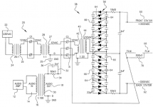
That inverted circuit you posted is from the Final Whitepaper and is incorrect, incomplete, or may intentionally miss-leading as shown. The green resistor you circled should not be there or should at most be 100K or so. The other two resistors should be 10Mohm, but should be on the other side of the 0.047uF capacitors. Attached is image from their patent which should hopefully make more sense.
As you properly reasoned, a stacked inverted ESL would require an additional transformer.
Thank you Bolserst ! so i did exactly what actually suppose to be the schematic 🙂
i indeed put the resistors before the cap directly on the HV cascade output then to the caps. and from caps to stator.
i can imagine a few K on that green might reduce potential huge current to occur when flashing over? i noticed it works a bit like a low pass when using bigger values just like it would on the membrane.
Thx for clearing the stacked idea up 🙂 i was afraid of that hehe. but it does mean a potential normal stepup trafo with center tap could be used to feed the alternating foils. in a stacked setup. only after more then 2 stacks it becomes more efficient for a given space then using the the trannies as a higher stepup ratio in a normal inverted esl. since that would yield 6dB and a stacked version of 2 foils with half the stepup would also result in 6dB.
🙁 so using [+bias] FOIL [-Bias] [few mm space] [+bias] FOIL [-bias] would still be 6 db more efficient then either of the above. but of course limits the upper frequencies range.
thanks for clearing this all. pheeeuw i finaly can just use it and dont have to feel i am making a mistake somewhere. 🙂 ill try a 10k resistor next time !
Last edited:
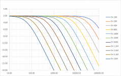
It will definitely help keep the current draw down which could save your amplifier if it doesn't have good over-current protection. Yes, the resistor produces a first order LP filter in combination with the panel capacitance. This can be used to help equalize the naturally rising HF response of ESLs.i can imagine a few K on that green might reduce potential huge current to occur when flashing over? i noticed it works a bit like a low pass when using bigger values just like it would on the membrane.
The 3dB down point is: f = 1/(2*Pi*R*C).
An example plot for 250pF panel with range of R values is attached.
Attachments
ah nice bolserst, as in my final design i would not use any resistor i gues , since i wnat to devide it on the foil, and the less i use the smaller semgents i can use i guess. so a tiny one for 15khz and up etc etc etc
i do thinkn 10 meg might not be enought for the HV + and -. i try to bump that to 20 or more, so it wont evaporate my alu when it does go wrong. i must add usually it went wrong because one of the biases did not work propper. so the foil really wanted to spark to one of the stators. and it sparks hard like really really loud spark and boom the alu evaporated 🙂 not even a hole to be seen
i do thinkn 10 meg might not be enought for the HV + and -. i try to bump that to 20 or more, so it wont evaporate my alu when it does go wrong. i must add usually it went wrong because one of the biases did not work propper. so the foil really wanted to spark to one of the stators. and it sparks hard like really really loud spark and boom the alu evaporated 🙂 not even a hole to be seen
Last edited:
Look, energy of the discharge depends on volts square and capacitance of the "segment". Resistance of the feeding resistor would not matter.
Look, energy of the discharge depends on volts square and capacitance of the "segment". Resistance of the feeding resistor would not matter.
hmm well , that might be but without resistors on the biases it does BIG BIG BANGS instead of with resistors that just makes sort of a lightning in one of those lightning balls. without resistor its a hard and loud snap. and the alu is gone BOOM
Last edited:
- Status
- Not open for further replies.
- Home
- Loudspeakers
- Planars & Exotics
- Inverted stacked esl ?