ok ,after reading the stuff from final i thought i give it a go.
First of all i dont want to start a discussion abouit the distortion being more or less then a classic design, just want to try this more efficient way. means less stepup count.
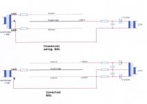
well here first picture is the concept of the final inverter tech.
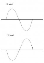
second picture is what i thought it should look like in practice. am i correct ? or do i not only change the polarity of the diodes but also switch the wires from the power so the sinus 230 looks like picture number 3. because then i have 2 opposite powers against eachother at all time. one stator is positiv and other negative?
i tried this once with my step up trafo and HS units but did not succeed, maybe my coating had to high resistance. looked like it worked only with one stator on the Hs unit.
well every comment or input is welcome, more or less destortion we might be able to still make a cheap high efficient tweeter that has less distortion then a dynamic driver.
First of all i dont want to start a discussion abouit the distortion being more or less then a classic design, just want to try this more efficient way. means less stepup count.
well here first picture is the concept of the final inverter tech.
second picture is what i thought it should look like in practice. am i correct ? or do i not only change the polarity of the diodes but also switch the wires from the power so the sinus 230 looks like picture number 3. because then i have 2 opposite powers against eachother at all time. one stator is positiv and other negative?
i tried this once with my step up trafo and HS units but did not succeed, maybe my coating had to high resistance. looked like it worked only with one stator on the Hs unit.
well every comment or input is welcome, more or less destortion we might be able to still make a cheap high efficient tweeter that has less distortion then a dynamic driver.
Attachments
I am very interested in this technique and curious if it will work well.
I'm also wondering if Martin Logan uses the same or a similar configuration,as the schematics I have seen also use a single secondary winding.
Also a very high diagphram resistance maybe an issue with this type of configuration.
It would be very intresting to find out if any one has had any experience with this type of setup.
If you swapped the polarity on the input of hs unit 1 and flipped all of the diodes so that they are going the other direction, this would give you +hv and it would work in conjuction with hs unit 2 (a -hv) as a high voltage bipolar supply.
With the ground referenced to the input of the capacitors as the schematic shows but with the changes I had already mentioned.
I had bought some aluminiumized mylar once to try this technique.
Only I never got around to tryin it,but I still might as I still have the material. jer
Only I never got around to tryin it,but I still might as I still have the material. jer
yeah so , swap the input power and the diodes?? so not like the schematic from final where only the diodes are swapped?
and yeah im gone try it with some mylar with damped aluminium on it as well, if i can get it somewhere in the netherlands.
with my high res coating the sound whas nothing !! only when i used one of the HS units there whas a little bit of sound, and with both turned on i only heared a 50 hertz buzz.
would a coating with graphite also work ? , i know the restistance could form a low pass filter. but maybe it will create a strip for high freuqency's near the copper strip to allow high frequencys only. so you dont need to sigment. other thing i whas looking for is using the alu mylar and then use S39 an accid used to solder metal,, to ereace some of the aluminium to segment the membrane.
Last edited:
I'm not sure what you mean with the graphite?
The aluminium has such a low resistance I don,t think it would make any difference.
To remove any aluminium from the surface just use a weak solution of sodium hydroxide (lye).
Just as would do too etch a pc board, as lye will clean but not etch copper just in case you were wondring. jer
The aluminium has such a low resistance I don,t think it would make any difference.
To remove any aluminium from the surface just use a weak solution of sodium hydroxide (lye).
Just as would do too etch a pc board, as lye will clean but not etch copper just in case you were wondring. jer
yeah so , swap the input power and the diodes?? so not like the schematic from final where only the diodes are swapped?
and yeah im gone try it with some mylar with damped aluminium on it as well, if i can get it somewhere in the netherlands.
with my high res coating the sound whas nothing !! only when i used one of the HS units there whas a little bit of sound, and with both turned on i only heared a 50 hertz buzz.
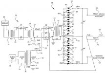
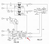
See Figure 4 from the Final Patent (US7054456) for correct way to orient the diodes in the two HV supplies to get + and - polarities on the stators.
Also notice they have a low pass filter on both of the supplies (10M resistor and 4nF capacitor) to reduce hum level.
Attachments
Last edited:
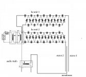
What is the point of using 3 power transformers in series if the end result is essentially wall voltage into the HV board?
in my image its two for the hs and one for audio. the 2 in the hs is because its a save current , you can leave those 2 away if you like but it aint as save as this ! first transforms from, 230 to 12 volt and the second 12 volt to 230, but because the transformers is limited in current its save.
What is the point of using 3 power transformers in series if the end result is essentially wall voltage into the HV board?
I'd assume it is to meet some safety regulation concerning isolation frame mains voltage.
Execellent,Steve!
Now I need to come up with a 10kv to 15kv filter cap for my supply. jer
More recent Final ESLs have used high frequency Royer oscillators to feed their voltage multipliers. This avoids the need for the low pass filter. A cheap source for DIY ready HV Royer oscillators can be found in CCFL drivers available from many online electronic supply distributors.
http://www.diyaudio.com/forums/plan...ge-bias-diy-electrostatics-3.html#post2098459
Actualy the supply I built is a switcher with a frequency of around 200khz and I'm feeding the panels through a 2.2meg resistor or should I increase it.
I do notice that more current seems to be drawn off of it at high diagphram execursions.
By monitoring the waveform going into the multiplier stage,its level changes slightly lower as more current is drawn from the supply.
Although it is not noticeable could this be causing a slight compression of the sound at high peaks?
It seems to work pretty good as it is or should I redesign it to produce more current?
If so would just increasing the value of the caps in the multiplier stage do the trick?
They are .0047uf with 1N4007 diodes. jer
They are .0047uf with 1N4007 diodes
It might not matter in this application but a 1n4007 has a large reverse recovery time and is not typically not suitable for use at 200kHz.
If you can use an ultra fast diode like a UF4007 you won't have any reverse recovery issues.
http://www.fairchildsemi.com/ds/UF/UF4005.pdf
Yes I did take that into consideration,but I didn't have any laying around.
So since all of the test data I have found was at 1mhz I decided to try a fullwave and half wave configuration and it seemed to work fine ,so I used them.
And if the recovery time became an issue I could have just lowered the frequency. jer
So since all of the test data I have found was at 1mhz I decided to try a fullwave and half wave configuration and it seemed to work fine ,so I used them.
And if the recovery time became an issue I could have just lowered the frequency. jer
Last edited:
Hi,
I assume there´s a slight lack of understanding the principle of this inverted ESL. The 4nF caps do of course filter the ripple of the HV-supplies. But just for filtering their value is grossly oversized. In terms of safety a considerably smaller cap would be sensitive. In case the Stator coating would fail the cap could shove all it´s stored energy into a touching body. So the caps must be of a small enough value that their stored energy does not reach potentially lethal levels.
But the caps serve another and much more vital task and that is the reason they need to be of quite large value. They close the AC-current loop. Without the caps the ESL wouldn´t work at all. Since the caps are connected in series with the ESL´s capacitance they form AC-voltage dividers. To keep the voltage drop over the cap low enough it must be of at least 5-10times the ESL´s capacitance value.
jauu
Calvin
Yes, it doesn't work at all with conventional high resistance coatings.
I would agree. As far as I can tell, to get low distortion with an ESL it needs to be run in "constant charge" mode. That is, the diaphragm is very high resistance, so that when it flexes from one side to another with the audio signal, the resistance is high enough to prevent the charge migrating to the region of the diaphragm that has (temporarily) the highest capacitance to one of the stators.
if you drive the diaphragm itself with the audio signal (rather than push-pull drive to the stators), you need to use a low resistance coating on the film, and so the "constant charge" mode of operation will be lost. The concept in the drawing will work, but the distortion will be higher than in a "Peter Walker" design.
Hi,
I assume there´s a slight lack of understanding the principle of this inverted ESL. The 4nF caps do of course filter the ripple of the HV-supplies. But just for filtering their value is grossly oversized. In terms of safety a considerably smaller cap would be sensitive. In case the Stator coating would fail the cap could shove all it´s stored energy into a touching body. So the caps must be of a small enough value that their stored energy does not reach potentially lethal levels.
But the caps serve another and much more vital task and that is the reason they need to be of quite large value. They close the AC-current loop. Without the caps the ESL wouldn´t work at all. Since the caps are connected in series with the ESL´s capacitance they form AC-voltage dividers. To keep the voltage drop over the cap low enough it must be of at least 5-10times the ESL´s capacitance value.
hi calvin,
Thanks for pointing out the true purpose of the large capacitors in the Final inverted ESLs. This makes perfect sense.
Without them the majority of the stepped-up audio signal would be dropped across the HV supplies rather than across the ESL where it can produce sound.
I now see they are indeed used in their latest patent application even with the high frequency used in the HV supply.
In fact, they are even larger in value at 10nF. This is about 8 times larger than the 1200pF of the larger section of the ESL.
Attachments
Membrane resistance
I've recently "unbuilt" a Final inverted speaker. Membrane resistivity is >1MEG Ohm square.
Considering the capacitors and transformer secondaries are ideal voltage source for audio frequencies, there is no difference if they are interchanged respectively.
Either way, the diapraghm charge remains constant and the stator voltages are modulated around this reference with the EHT bias in series to compensate for charge leakage.
- Status
- Not open for further replies.
- Home
- Loudspeakers
- Planars & Exotics
- inverted ESL