Awesome, if i can suggest, dont anodize in black ... try gold or maybe polish all the way - then clear anodizing ... but, gonna be awesome when you finish ....
Awesome, if i can suggest, dont anodize in black ... try gold or maybe polish all the way - then clear anodizing ... but, gonna be awesome when you finish ....
Choices, choices, choices... 😱 😕

I'd really like to be able to see the milling holograms when the finish is applied.
I think champagne anodizing for the body with a high gloss clear anodized front plate...? But then again, i don't know what i really like for this thing! grrrr....
Perhaps like the champagne/gold Iphones?
Here they are: PHOTOGRAPHS!
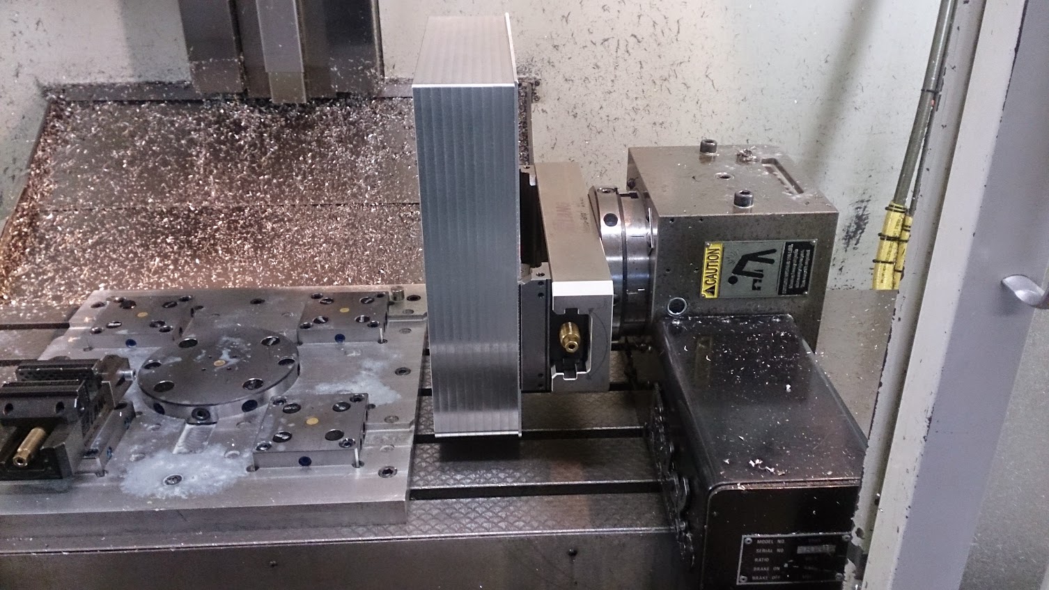
Today i had the pleasure of using this machine, it's a Haas VM3, my regular machine was occupied so i moved to this one:
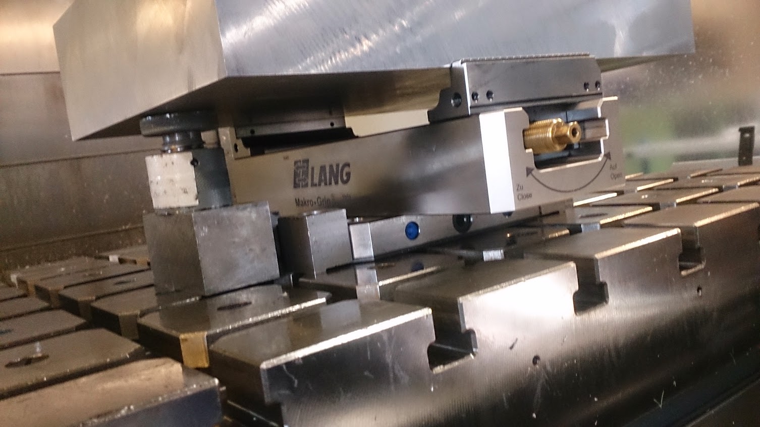
Fixed the base plate on the machine bed so the vice can be attached:

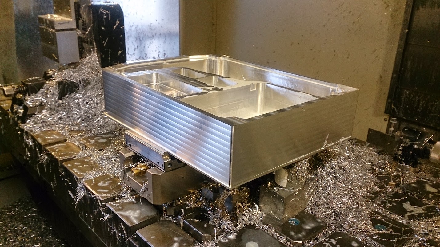
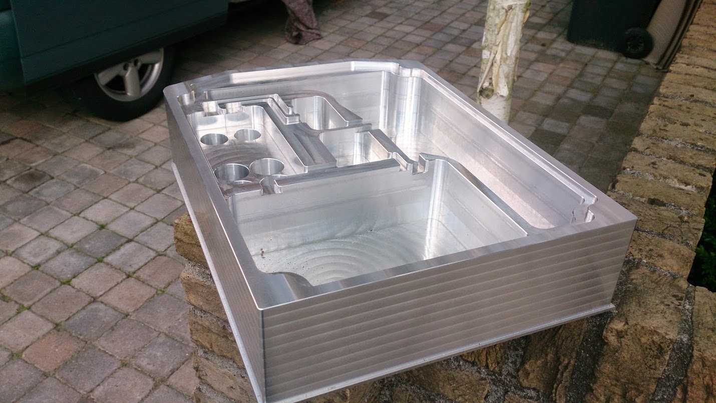
And there it is, a little more than 30KG of aluminum:
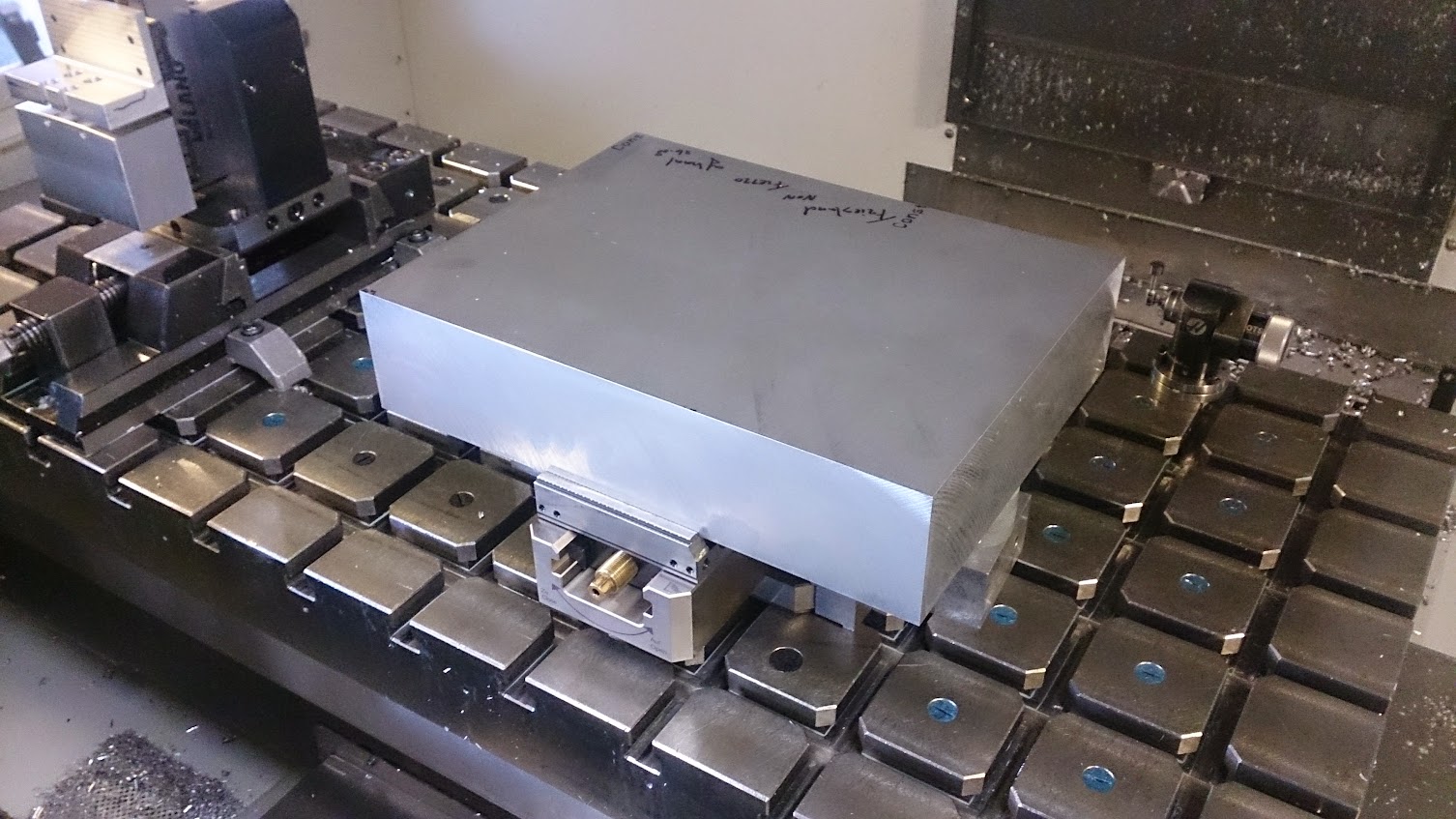
On the left and right a jackscrew to eliminate any vibration
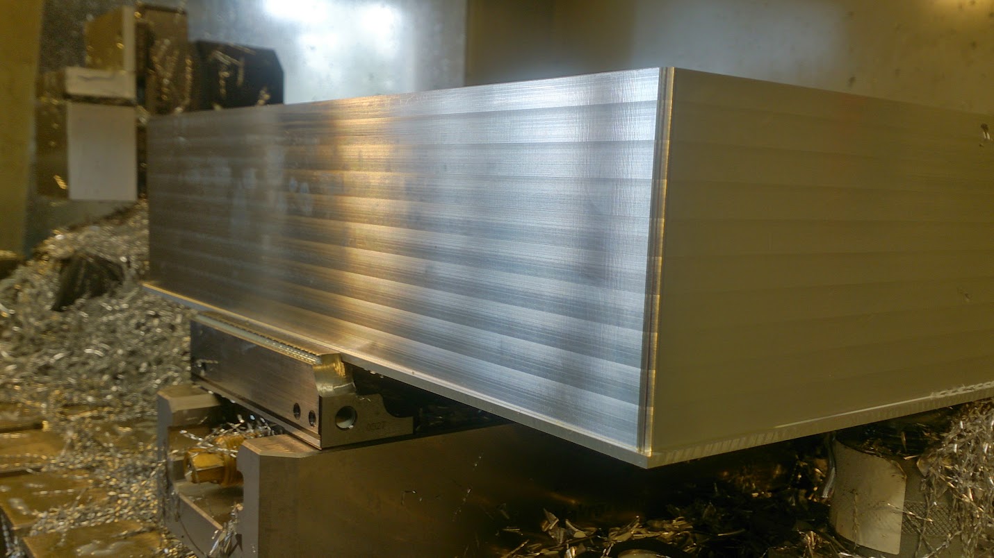
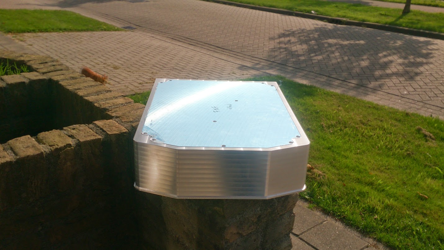
First setup, facing the top and roughing the corners. Facing was done identical as the front plate, they really match 🙂

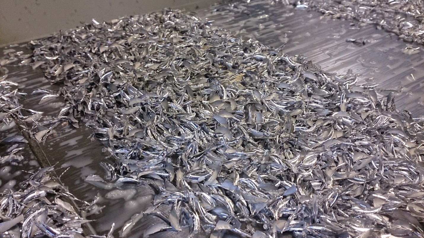
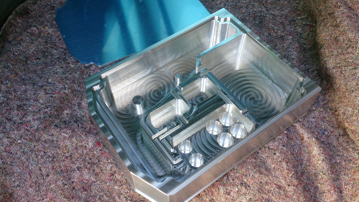
Milled the outside and roughed the inside:


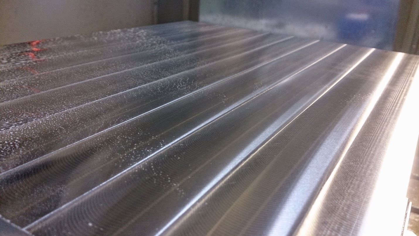
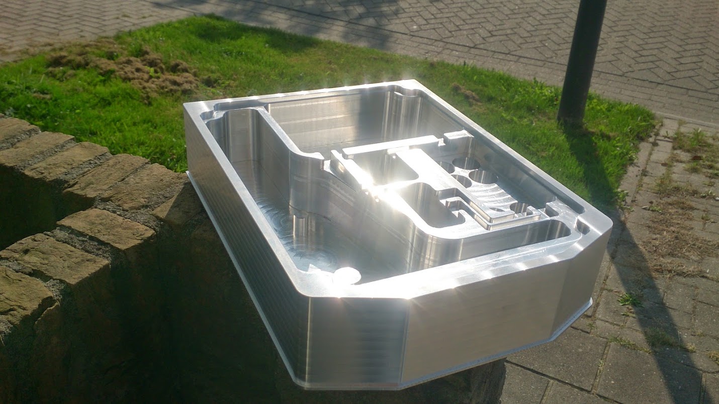
Finished the sides of the pockets:
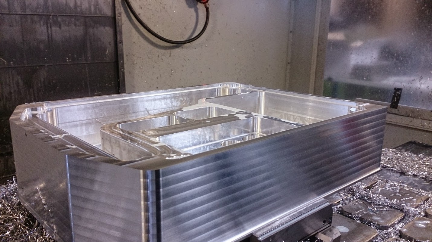
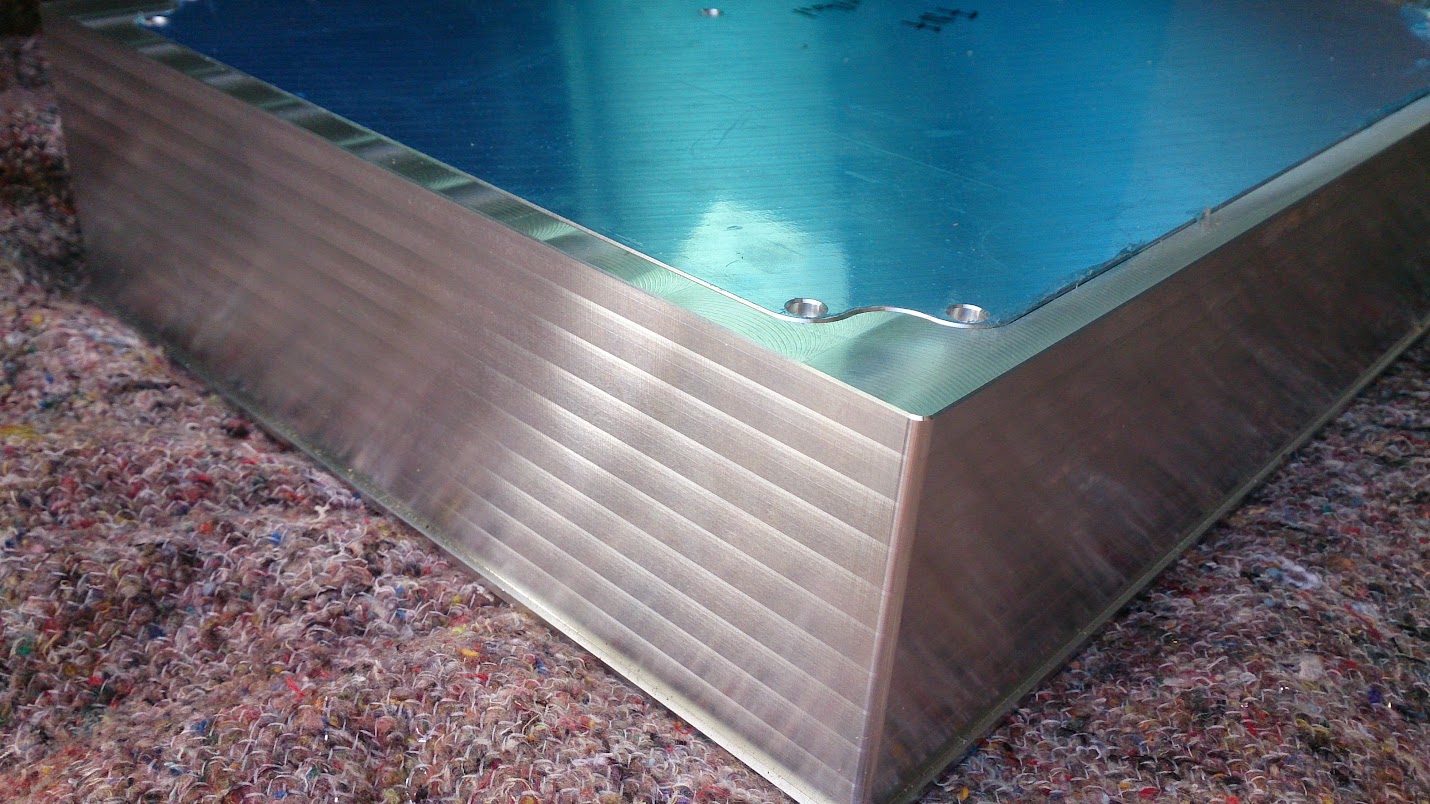
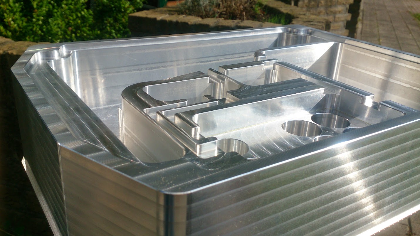
Unfortunately i couldn't finish the whole setup, i still need to put some threaded holes and fillets on the edges of the grooves. But asides that it's all finished nicely and i've put a nice subtle chamfer on every edge.


Well, these where the pic's of today..
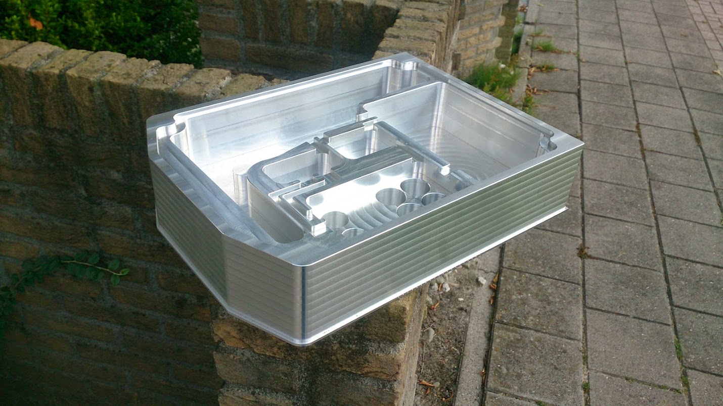
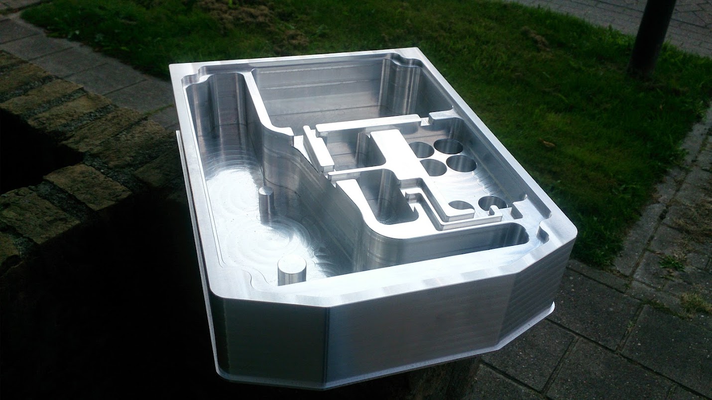
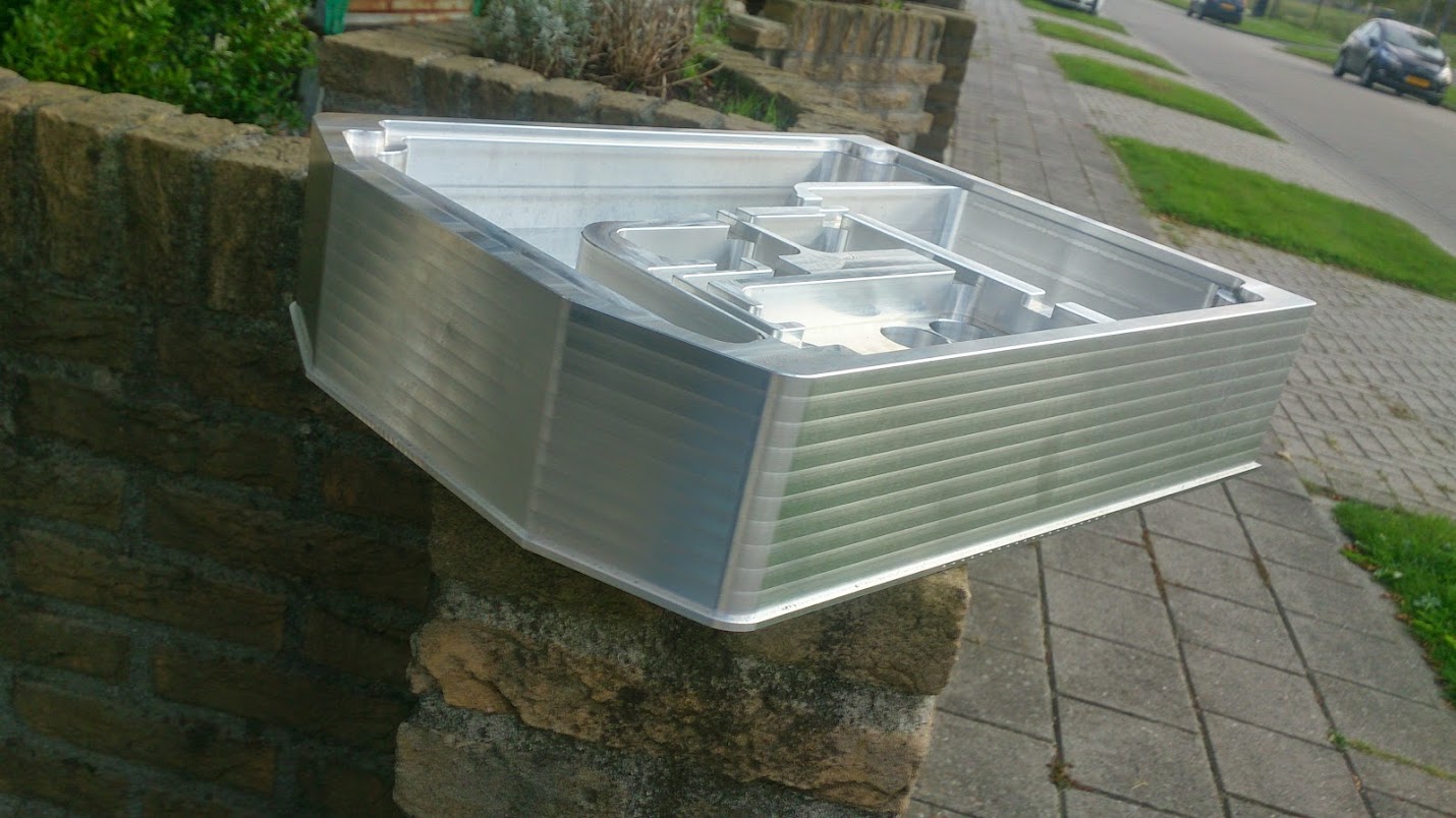
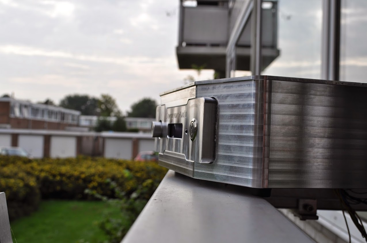
I'm quite impressed by the result, eventhough i see pretty products every day, this is really something special. Not because i designed it or i made it, but it was made to be eye candy.
But the best is ahead of us, the top side.
Later i'll post some high-res pictures! Thanks for watching, i hope you enjoyed it!
Today i had the pleasure of using this machine, it's a Haas VM3, my regular machine was occupied so i moved to this one:
An externally hosted image should be here but it was not working when we last tested it.
Fixed the base plate on the machine bed so the vice can be attached:
And there it is, a little more than 30KG of aluminum:
On the left and right a jackscrew to eliminate any vibration
First setup, facing the top and roughing the corners. Facing was done identical as the front plate, they really match 🙂
Milled the outside and roughed the inside:
An externally hosted image should be here but it was not working when we last tested it.
An externally hosted image should be here but it was not working when we last tested it.
Finished the sides of the pockets:
An externally hosted image should be here but it was not working when we last tested it.
Unfortunately i couldn't finish the whole setup, i still need to put some threaded holes and fillets on the edges of the grooves. But asides that it's all finished nicely and i've put a nice subtle chamfer on every edge.
An externally hosted image should be here but it was not working when we last tested it.
An externally hosted image should be here but it was not working when we last tested it.
Well, these where the pic's of today..
I'm quite impressed by the result, eventhough i see pretty products every day, this is really something special. Not because i designed it or i made it, but it was made to be eye candy.
But the best is ahead of us, the top side.
Later i'll post some high-res pictures! Thanks for watching, i hope you enjoyed it!


Choices, choices, choices... 😱 😕
I'd really like to be able to see the milling holograms when the finish is applied.
I think champagne anodizing for the body with a high gloss clear anodized front plate...? But then again, i don't know what i really like for this thing! grrrr....
Perhaps like the champagne/gold Iphones?
How abut, everything high gloss natural, just faceplate champagne, buttons and pots also natural high gloss
Only thing i will do, and you go different way - i will make separate pocket for transformers and fill them with potting compound ... but is minor thing ...
But you can still make aluminum covers for transformers, fill them with potting compound and screw them on the place upside-down ...
But you can still make aluminum covers for transformers, fill them with potting compound and screw them on the place upside-down ...
Last edited:
Only thing i will do, and you go different way - i will make separate pocket for transformers and fill them with potting compound ... but is minor thing ...
But you can still make aluminum covers for transformers, fill them with potting compound and screw them on the place upside-down ...
Anyway, what ever choice you made, is gonna be awesome enclosure ...
How abut, everything high gloss natural, just faceplate champagne, buttons and pots also natural high gloss
I'll keep the options in mind.. I think it's easier to make a choice when then whole model of the case is done ;-)
Thanks for the input though!
Looks amazing. Was the front of the larger piece not meant to have a recess in it for the front panel?
Looks amazing. Was the front of the larger piece not meant to have a recess in it for the front panel?
Yup, the case isn't finished yet ;-)
It took a while today to finally upload the pictures, but here they are.
I started this morning by putting the block in the 4th axis
It barely fit
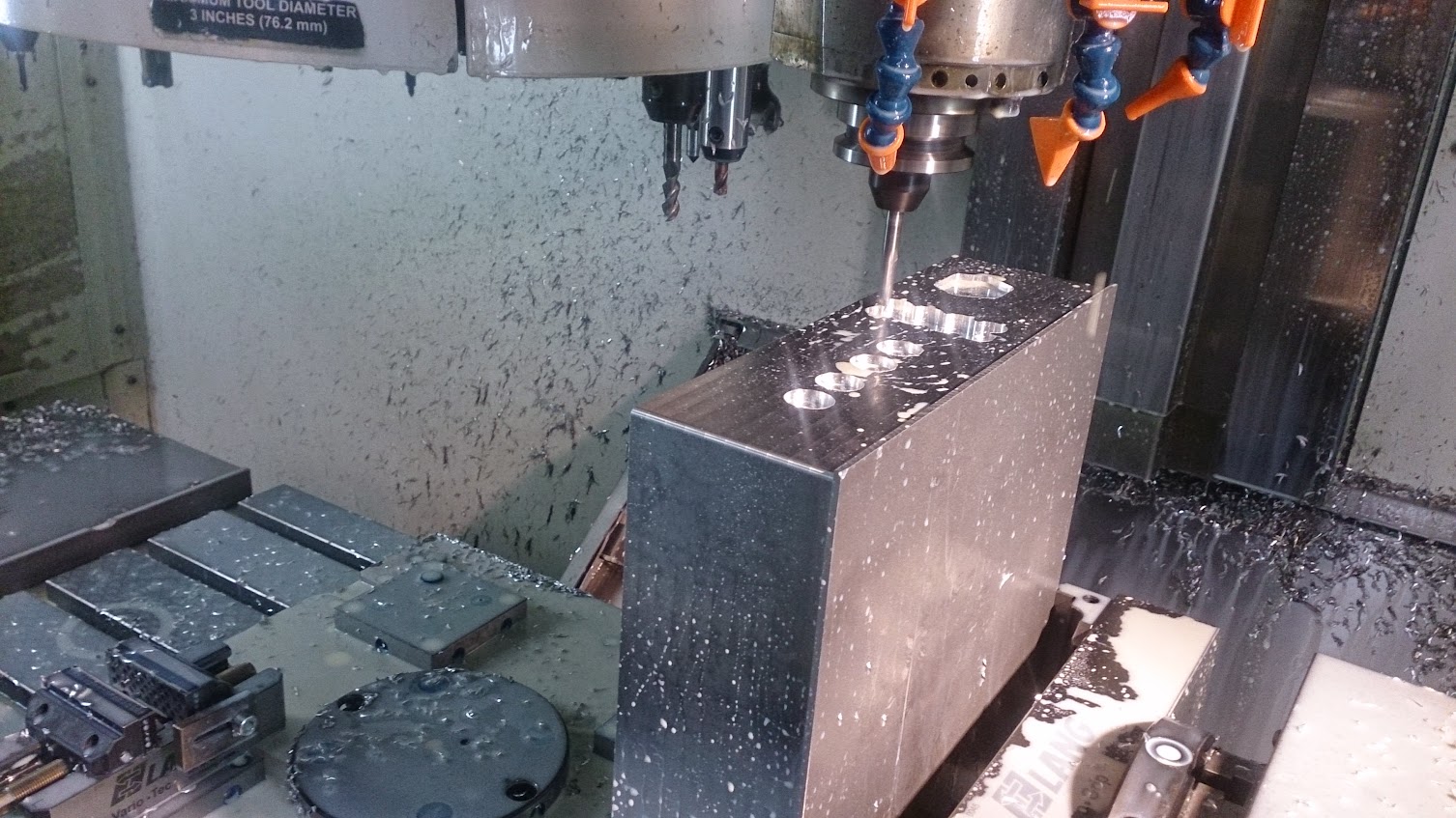
And started milling the backside of the amplifier

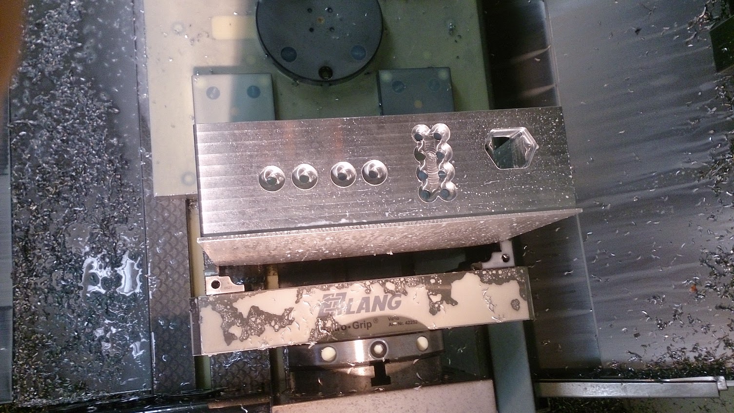
Also deburring on the inside, it's a great little tool, safe's me a lot of work 🙂
Testing if it fits

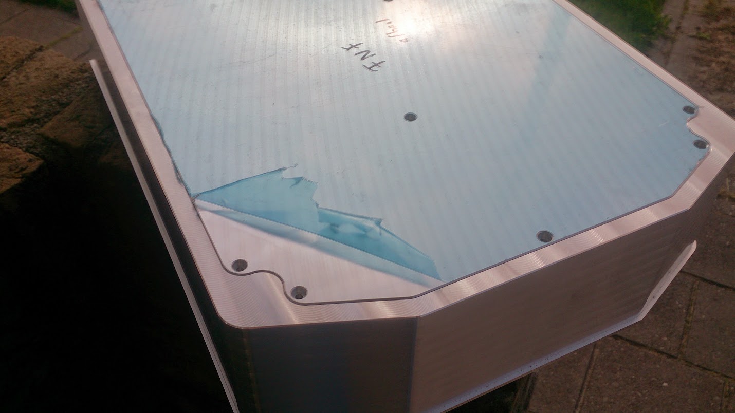
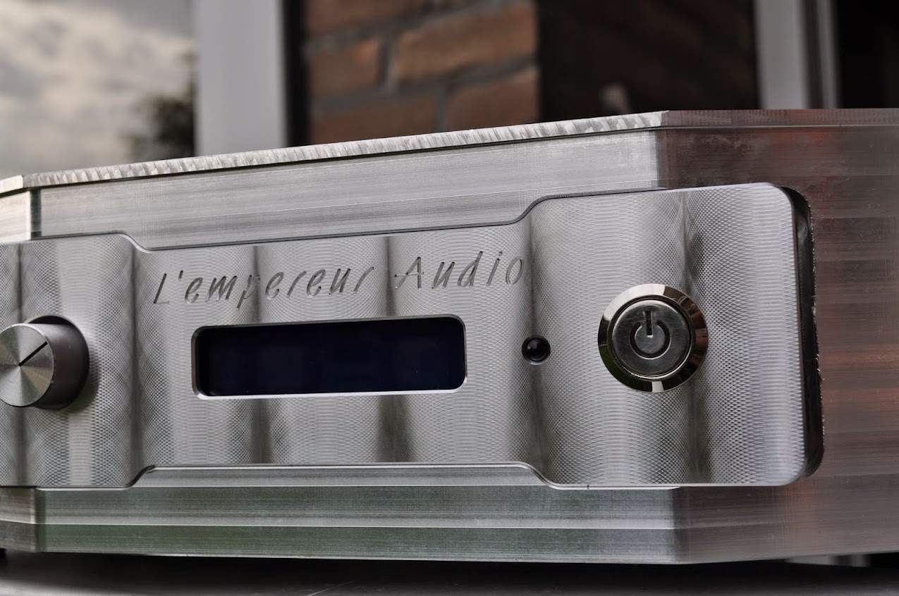
And of course, engraving! Need to have some text every here and there :green:
And i milled the front, this didn't really went as expected. During machining it pushed the block through the brake of the 4th axis.
This made the block rotate slightly, but enough to make the pocket too big.
I put some jackscrews under the vice to prevent this from happening again. Now i've made the pocket a big bigger on purpose to make it straight again.
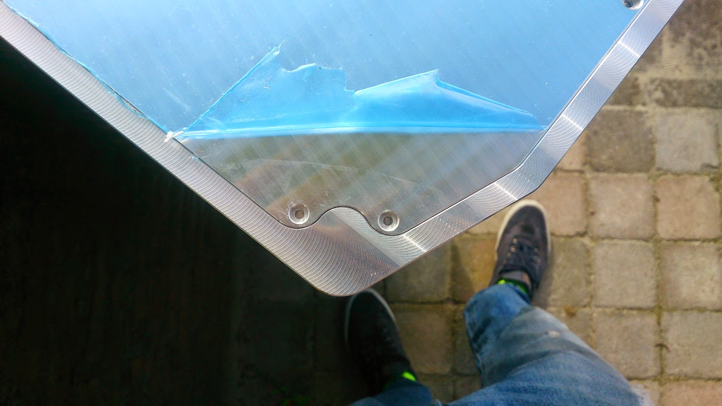
Of course it's too big for the front to fit nicely. So i'll have to make a new front, this is O.K. because i don't really like the name i put there.
So please don't mind the gap between the case and the front, it will be fixed 😱
And a few more pictures post machining
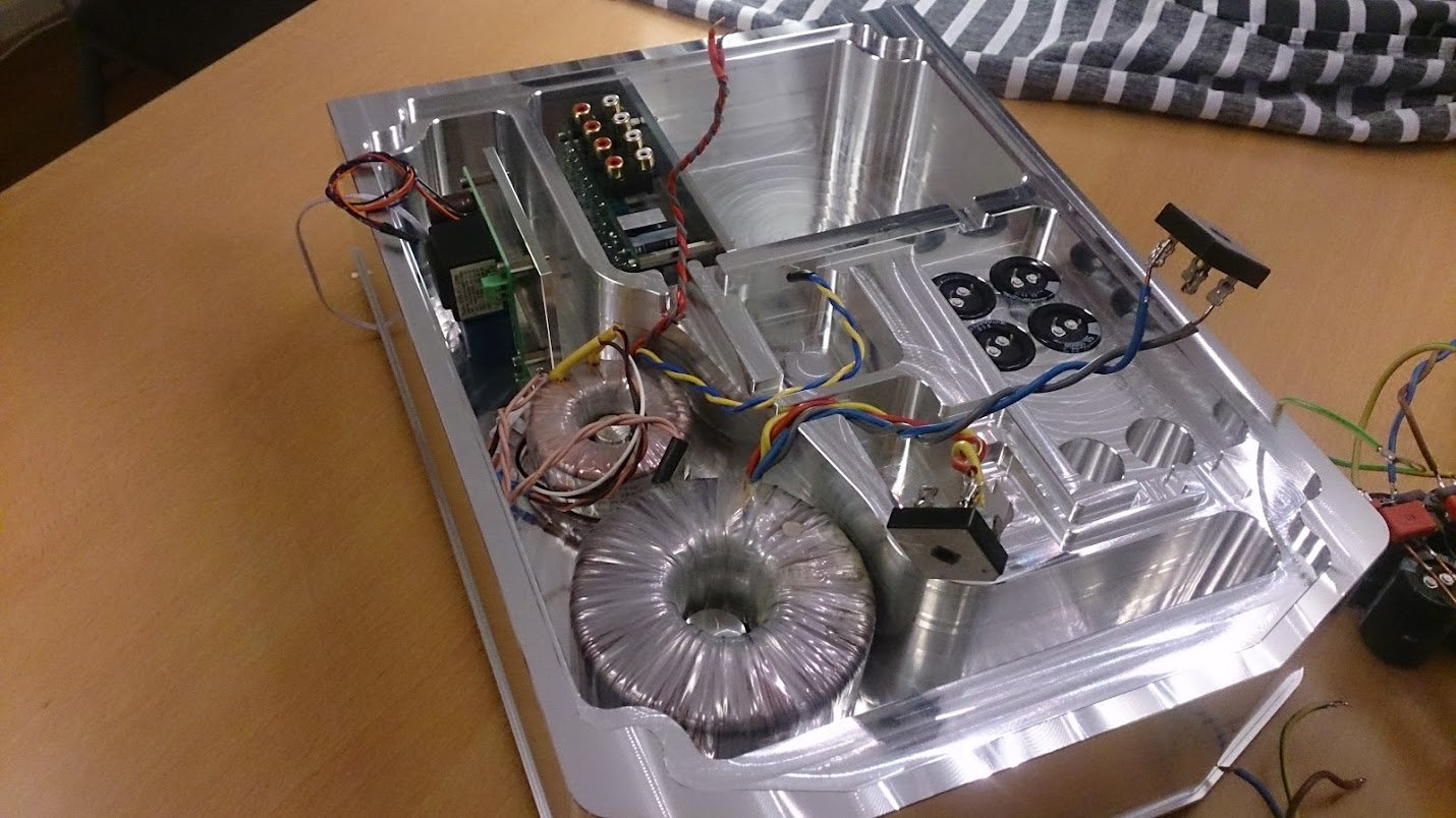
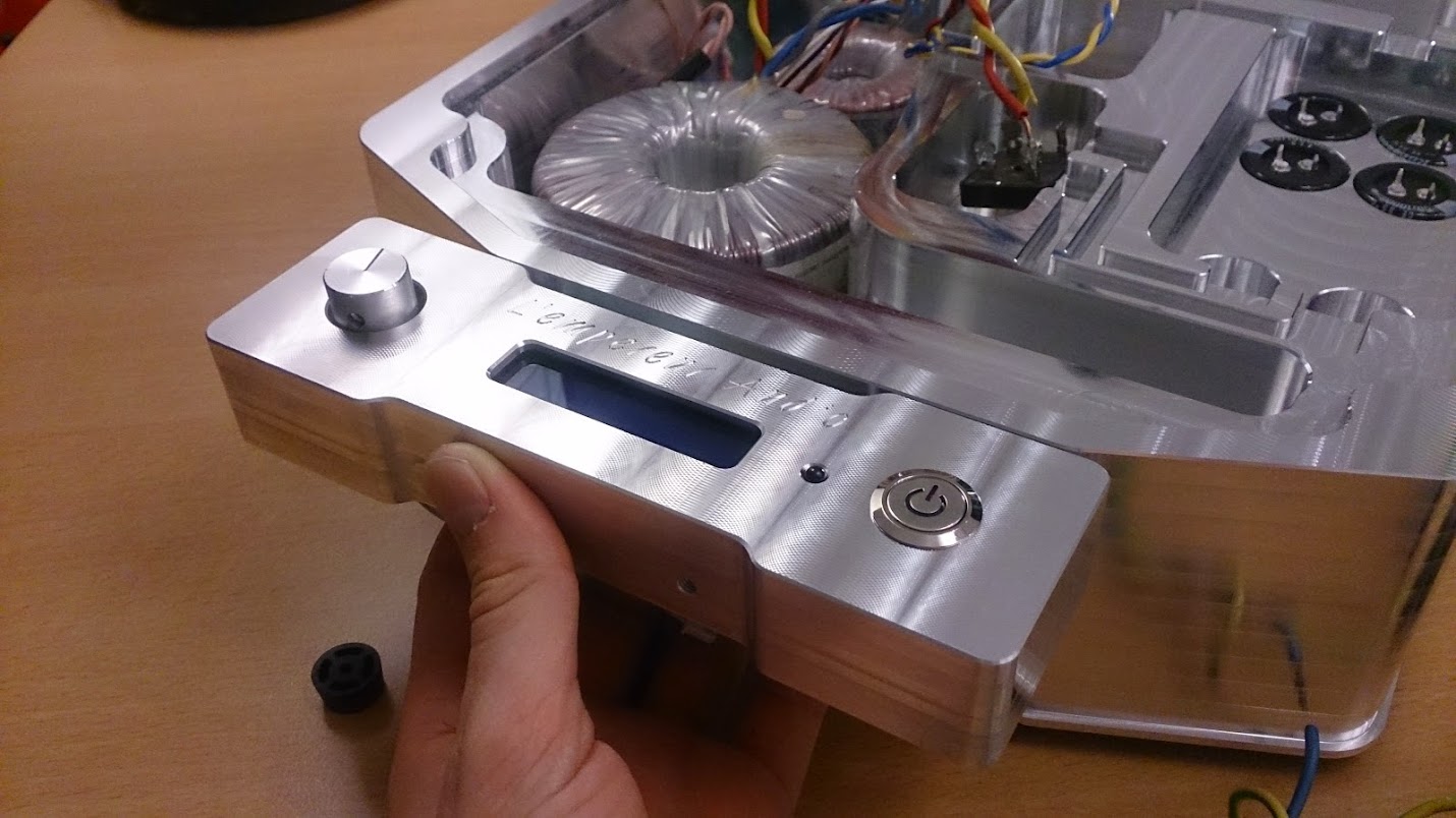
Pictures after i switched to a proper camera:

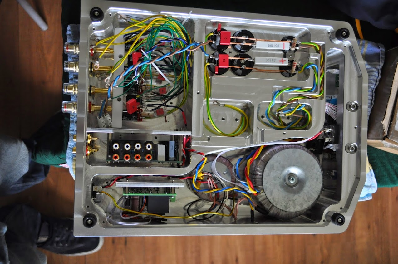
Yes, Yes, i know, something's not right there, the bracket of the PCB is in front of the hole for the RCA socket. I'll adjust the bracket later so it'll fit properly....
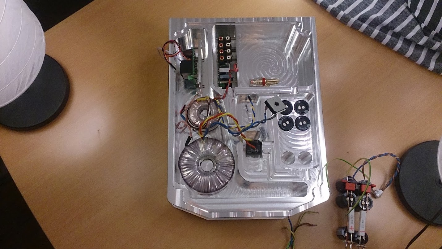
Yup, indeed, there will be a new front later.


This bracket is causing the trouble
Well, that's it for now, i'm pretty happy with the result 8)
I started this morning by putting the block in the 4th axis
An externally hosted image should be here but it was not working when we last tested it.
It barely fit
An externally hosted image should be here but it was not working when we last tested it.
And started milling the backside of the amplifier
An externally hosted image should be here but it was not working when we last tested it.
An externally hosted image should be here but it was not working when we last tested it.
Also deburring on the inside, it's a great little tool, safe's me a lot of work 🙂
An externally hosted image should be here but it was not working when we last tested it.
Testing if it fits
An externally hosted image should be here but it was not working when we last tested it.
And of course, engraving! Need to have some text every here and there :green:
An externally hosted image should be here but it was not working when we last tested it.
An externally hosted image should be here but it was not working when we last tested it.
And i milled the front, this didn't really went as expected. During machining it pushed the block through the brake of the 4th axis.
This made the block rotate slightly, but enough to make the pocket too big.
I put some jackscrews under the vice to prevent this from happening again. Now i've made the pocket a big bigger on purpose to make it straight again.
Of course it's too big for the front to fit nicely. So i'll have to make a new front, this is O.K. because i don't really like the name i put there.
So please don't mind the gap between the case and the front, it will be fixed 😱
An externally hosted image should be here but it was not working when we last tested it.
And a few more pictures post machining
An externally hosted image should be here but it was not working when we last tested it.
An externally hosted image should be here but it was not working when we last tested it.
Pictures after i switched to a proper camera:
An externally hosted image should be here but it was not working when we last tested it.
An externally hosted image should be here but it was not working when we last tested it.
An externally hosted image should be here but it was not working when we last tested it.
Yes, Yes, i know, something's not right there, the bracket of the PCB is in front of the hole for the RCA socket. I'll adjust the bracket later so it'll fit properly....
An externally hosted image should be here but it was not working when we last tested it.
An externally hosted image should be here but it was not working when we last tested it.
An externally hosted image should be here but it was not working when we last tested it.
An externally hosted image should be here but it was not working when we last tested it.
An externally hosted image should be here but it was not working when we last tested it.
Yup, indeed, there will be a new front later.
An externally hosted image should be here but it was not working when we last tested it.
An externally hosted image should be here but it was not working when we last tested it.
An externally hosted image should be here but it was not working when we last tested it.
An externally hosted image should be here but it was not working when we last tested it.
An externally hosted image should be here but it was not working when we last tested it.
An externally hosted image should be here but it was not working when we last tested it.
An externally hosted image should be here but it was not working when we last tested it.
An externally hosted image should be here but it was not working when we last tested it.
This bracket is causing the trouble
An externally hosted image should be here but it was not working when we last tested it.
An externally hosted image should be here but it was not working when we last tested it.
Well, that's it for now, i'm pretty happy with the result 8)
Wow, that's amazing! Excellent work. Is it fully functional now? What did the large piece of aluminium cost?
Wow, that's amazing! Excellent work. Is it fully functional now? What did the large piece of aluminium cost?
I still need to make the top, with the cool ribs 😉
It was already fully functional, but now the electronics have a new house 🙂
I need to make a few minor adjustments and a new front and she's ready for anodizing.
Can't wait until i can finally listen to this amp again 🙂
Materials cost where over €300,- The big block and the tooling plate for the cover alone where already €250,- excluding tax 😡 A bit more expensive than I expected..
Hi HowlindawgThis looks fantastic.
How many man hours have gone into crafting the enclosure so far?
Thanks for your reply.
I think roughly 30-35 hours of actually machining. And I think about a day more.
And of course many hours of designing. But so far, it was really worth it 🙂
I've made a new front this evening (european time :wink🙂. This one is a bit wider, so it fits properly in the hole of the case that got a bit too big.
I've been playing a bit with the "old" front, a bit of polishing, but i'm not sure what to think of it. I don't think it leaves a nice finish.
But perhaps a bit of light polishing is a good pre-anodizing treatment...
An externally hosted image should be here but it was not working when we last tested it.
An externally hosted image should be here but it was not working when we last tested it.
An externally hosted image should be here but it was not working when we last tested it.
I've been playing a bit with the "old" front, a bit of polishing, but i'm not sure what to think of it. I don't think it leaves a nice finish.
But perhaps a bit of light polishing is a good pre-anodizing treatment...

- Status
- Not open for further replies.
- Home
- Amplifiers
- Chip Amps
- Introduction and project info