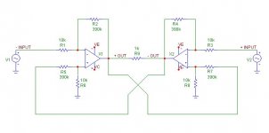
This is my understanding of the X-circuit:
To achieve X-supersymmetry you need two inverted amplifiers and feedbacks from the other amplifiers.The two operational amplifiers work as subtracting circuits where the output voltage of the op-amp is the amplified difference of the voltages presented at the inverted and non-inverted inputs.The voltage at the inverted input is the input voltage, and the voltage on the non-inverted input is the feedback signal from the output of the second op-amp which is in oposite phase with the input signal. By crossing the feedbacks you tend to simetrize the distortions in the both amplifiers and cancel them on the load because they are in oposite phases.
I think that what I said above is correct, but if something is not,
please correct me.
Bricolo,
I have given your last scematic some more thoughts, and I tend to believe that you have got some X, not because you have drawn it, but because it seems you get the noice produced in each opamps to apear on the diffrential outputs in common mode and thus cancled, and kept the signal in differetial mode, in this way you have separated noice and distortion from the signal. But how well the noice and distortion is canclled, I don´t know.
I have to think it over a little more and the intresting thing is that you achieve the X in a little different way.
But I am also afraid that you will get the hall of mirrors effect, wich in turn can destroy the sound. But give it a try.
Nice try🙂
Nelson:
I splattered Pepsi all over my screen when I read this!
"girly-man chips" indeed 😀
mlloyd1
Hey, when are you gonna say more about that Class A Hafler DH220?
I splattered Pepsi all over my screen when I read this!
"girly-man chips" indeed 😀
mlloyd1
Hey, when are you gonna say more about that Class A Hafler DH220?
Nelson Pass said:My other idea involves using real transistors instead of
girly-man chips. 😉
Rookie said:To achieve X-supersymmetry you need two inverted amplifiers and feedbacks from the other amplifiers.The two operational amplifiers work as subtracting circuits where the output voltage of the op-amp is the amplified difference of the voltages presented at the inverted and non-inverted inputs.The voltage at the inverted input is the input voltage, and the voltage on the non-inverted input is the feedback signal from the output of the second op-amp which is in oposite phase with the input signal. By crossing the feedbacks you tend to simetrize the distortions in the both amplifiers and cancel them on the load because they are in oposite phases.
There aren't two opamps, rather there is a single differential
input pair which symmetrically receives feedback from the
balanced outputs in an inverting mode so that their inputs
are operated at virtual ground. Errors appear at this pair
of virtual grounds, and are communicated to each side
symmetrically via the connected Emitters/Source/Cathodes
of the diff pair.
Henrik said:Bricolo,
I have given your last scematic some more thoughts, and I tend to believe that you have got some X, not because you have drawn it, but because it seems you get the noice produced in each opamps to apear on the diffrential outputs in common mode and thus cancled, and kept the signal in differetial mode, in this way you have separated noice and distortion from the signal. But how well the noice and distortion is canclled, I don´t know.
I have to think it over a little more and the intresting thing is that you achieve the X in a little different way.
But I am also afraid that you will get the hall of mirrors effect, wich in turn can destroy the sound. But give it a try.
Nice try🙂
My previous answer was a joke! 😉
what is the hall of mirors effect?
Bricolo said:
My previous answer was a joke! 😉
what is the hall of mirors effect?
From the patent:
The amplifying process is recursive and iterative in nature, so that any error on the part of one amplifier stage in reproducing the error in the other results in additional error correction on the part of the original amplifier stage. In the absence of any coupling loss, the iterative process could go on indefinitely. If this were to occur, the small, but not insignificant, phase shift involved in the transit of the signal between the coupled amplifier stages could lead to a kind of "hall of mirrors" effect where the outputs -OUT and +OUT, when viewed non-differentially, would exhibit excessive distortion and noise, even though it might still have very good differential performance. The individual out-put signals would no longer resemble the input signals, especially at high frequencies, requiring a load at the receiving end having especially good common mode rejection to obtain the differential signal.
Nelson Pass said:
Errors
I was silly. I just got my errors very clearly.
Thanks, Nelson Pass.
😎
JH
Nelson Pass said:
There aren't two opamps...
I was commenting Bricolo's second schematic. What do you think about his second schematic Mr. Pass?
Regards,
Dejan
"There aren't two opamps, rather there is a single differential
input pair which symmetrically receives feedback from the
balanced outputs in an inverting mode so that their inputs
are operated at virtual ground. Errors appear at this pair
of virtual grounds, and are communicated to each side
symmetrically via the connected Emitters/Source/Cathodes
of the diff pair."
http://home.kimo.com.tw/skychutw/Circuits/Hadley622.pdf

Notice how distorted are the output voltages, but the distortions
are simetrical and canceled on the load. I don't know what occurs such a heavy distortion, but when I increase R5 and R7 to 391k, the distortion is gone!
are simetrical and canceled on the load. I don't know what occurs such a heavy distortion, but when I increase R5 and R7 to 391k, the distortion is gone!
I'm going to try to explain what I understood from X:
Imagine an amp, made of two symmetrical sides, one amplifies the "hot", the other the "cold"
at the output of one side, you have x.hot+a.distortion (x is the amplification factor, hot is the input voltage), on the other side, x.cold+b.distortion
that we want to do, is reinject a.distortion in the cold side, and b.distortion in the hot side, by taking an amount of the hot output, and inject it in the cold output (crossed feedback)
so on the cold output we have: x.cold+b.distortion+a.x.distortion
and on the hot output: x.hot+a+distortion+b.x.distortion
after that, we fix the feedback resistor's values to obtain b=-a.x and a=-b.x, so each sides's distortion (remember that each side hasn't exactly the same distortion, if they would have, X would be unusefull) is added to the other side's output
 of those trying to explain it?
Bricolo said:two symmetrical sides
It could have been better with the two sides communicating internally too...
JH
Fred was beating on my cage about this, so I spent some
time analyzing this. No, it doesn't qualify as an X, at least
as I can make out. (Anyone with a simulator is welcome
to prove me incorrect).
A2 functions as an error correction mechanism for A3, but
the function of the two is not symmetric. A2 typically
operates at a very low level, ideally only correcting the
output of A3. It does not carry signal otherwise.
A3 carries the main load, and in this regard is much like
the classic error correction circuits.
If you were to make a power amp of this, I would expect that
A2 would be a low voltage Class A and A3 would be a high
voltage AB, with both amplifiers having the same output
current rating. This description corresponds roughly to the
never-made-it-to-market Dayton Wright XEC1000 amplifier.
- Status
- Not open for further replies.
- Home
- Amplifiers
- Solid State
- Introducing the X-GainClone