Hi Bricolo,
Do you have the full version of simetrix, or are you using the demo?? If so how much did you pay for it if you dont mind me asking.
Cheers
Sheriff
Do you have the full version of simetrix, or are you using the demo?? If so how much did you pay for it if you dont mind me asking.
Cheers
Sheriff
I think existing suggestions from Nelson suggests that the X works with a small number if stages only and 3 kind of being the limit. If there are too many stages you would get the "infinite hall of mirrors" effect.
Nothing wrong in testing though. Simple enough to build and if doesn't work then it doesn't work.
Nothing wrong in testing though. Simple enough to build and if doesn't work then it doesn't work.
It will work, but it won't be an X circuit. The error of one
half is reproduced with the wrong phase to cancel.

half is reproduced with the wrong phase to cancel.

Nelson Pass said:It will work, but it won't be an X circuit. The error of one
half is reproduced with the wrong phase to cancel.

Ah! That's why lowering the "crossed resitors"'s values increased the gain

As a correction, I don't see anything else that connecting the "crosses resistors" to the non inverting inputs (that won't be connected to ground anymore, but certainly to a grounded resistor)
Another idea, Mr Pass?
Hmm.. I don´t get it, to me it seems like the errors actually will cancel as the chips is in inverted mode... no?
/Peter
/Peter
The general idea is, that you one way or the other, isolates errors from signal in such a way that the signal from one side is fed reversed and the errors fed nonreversed to the other side, then the errors appears in common mode and thus canclled and the signal in difrential mode thus amplified.
In your scematic I can´t see any separation between errors and signal wich is the first step to X. It works but no X.
🙂
In your scematic I can´t see any separation between errors and signal wich is the first step to X. It works but no X.
🙂
Henrik said:The general idea is, that you one way or the other, isolates errors from signal in such a way that the signal from one side is fed reversed and the errors fed nonreversed to the other side, then the errors appears in common mode and thus canclled and the signal in difrential mode thus amplified.
In your scematic I can´t see any separation between errors and signal wich is the first step to X. It works but no X.
🙂
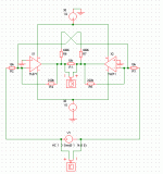
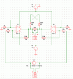
are you talking about my first shematic, the second, or both?
Briccolo
I am talking about both.
X is hard to understand, an it is also difficult to describe in general terms, but the separation between errors and signal is the first fundamental condition as I se it.
I am talking about both.
X is hard to understand, an it is also difficult to describe in general terms, but the separation between errors and signal is the first fundamental condition as I se it.
Quoting Nelson:
The essence is still using a symmetric feedback arrangement
around a differential pair, which isolates error from signal
and uses it to make distortion on two halves identically
in phase and thus cancelled.
🙂
The essence is still using a symmetric feedback arrangement
around a differential pair, which isolates error from signal
and uses it to make distortion on two halves identically
in phase and thus cancelled.
🙂
Bricolo said:
I think the X is stirred in.
But, what food would come out...?!?!
JH
PS. You should have been busy with school exams...?!?!
Oh,, whops! Now I see it, the frist chematic is "inverted to inverterd", no good 🙂
The 2nd seems to do the job.
/Peter
The 2nd seems to do the job.
/Peter
Bricolo,
A few months ago I drew a schematic that is almost identical to your second (only different resistor values), and I'm pretty sure that it can qualify as a X-amp.
A few months ago I drew a schematic that is almost identical to your second (only different resistor values), and I'm pretty sure that it can qualify as a X-amp.
Tell me what the X-qualifications are, explain the X rather than suggest, X does not come by it self, still I can´t see it.
🙂
🙂
Henrik said:Tell me what the X-qualifications are, explain the X rather than suggest, X does not come by it self, still I can´t see it.
🙂
don't you see an "X" on the shematic? with the crossed resistor wires? 😉
- Status
- Not open for further replies.
- Home
- Amplifiers
- Solid State
- Introducing the X-GainClone


