The most common case is of course - that the teleporter is used on both ends - and in that case J1 should ideally be closed.
In a case where the transmitter was not a teleporter 🙂 The teleporter can act act a pure receiver if configured that way.
What would a non-teleporter-transmitter be? I'm very curious. 😱😕
The most common case is of course - that the teleporter is used on both ends - and in that case J1 should ideally be closed.
This is rather confusing. I had dropout issues using the Teleporters when I tried them back in about 2013 or so. I see a J1 (which is open) on my v1.1 boards but I don't see J2. I would think the Teleporters should be supplied set up to be used in pairs.
I understand.
See section 3.2.3 here:
http://www.ti.com/lit/an/slla108a/slla108a.pdf
I simply wanted to design to be flexible enough to run type-1 or type-2.
I will try to make it clear that J1 should normally be installed. It's kind of tricky because the pins have an internal pull-up - so the default is type-2. I kind of wish they did it the other way around 🙂
Well I have to admit to being a bit irritated. This is the first I have heard of the need for a jumper at J1. I went back and re-read this entire thread. No mention of this. And I have not found any hint of the Teleporter manual that was promised early on. Where is J2? I don't see it on my boards. Does a manual exist?
J2 does not exist on older boards - it was introduced when we changed to shielded jacks. I will add a note on the first page. All J2 does is connect the jack shield to GND.
I actually thought there was a manual. I will do a little digging. If there isn't I will make sure to put one up!
I actually thought there was a manual. I will do a little digging. If there isn't I will make sure to put one up!
The most common case is of course - that the teleporter is used on both ends - and in that case J1 should ideally be closed.
Should it be closed on booth teleporters or just on receiver?
Also should J2 be closed on booth ends?
BR
Branko
Last edited:
J1 really only affects the receiving end. So I would only install it there.
For J2 - you can experiment here - but I would install it on both ends - and be sure to use shielded CAT5/CAT6 - otherwise it does no good.
Cheers!
Russ
For J2 - you can experiment here - but I would install it on both ends - and be sure to use shielded CAT5/CAT6 - otherwise it does no good.
Cheers!
Russ
Wow! So my first question is there any operational difference between V.1.1 and V.1.2?
I ask because both of my V.1.2 boards appear to be bad.
First it was lots of dropouts then the DAC wouldn't lock at all. I replaced the receiver with a 1.1 board and things worked for a while then when sending a 0dbfs tone to measure the outputs suddenly silence no lock. I happened to sense a very hot chip, the square multipin on the transmitter so suspected it had died. Just looking at resistance I can see pins 5-8 at ground on the 176333 bad receiver. Hypothesizing that the bad receiver stressed the transmitter and then the 0dbfs took it out completely?
In any case V1.1 teleporter now installed as transmitter and receiver with J1 shorted on the receiver and J2 shorted on both. My test CAT 5 cable is not shielded so I connected grounds together. Beautiful music again. Still momentary dropouts when the refridgerator cycles but thats just my poor power here. On a more positive note the first two DACs running with the same Mercury are very close 1.05 - 1.07 db I have the Mercury Rs at 27 ohm due to the gain of the amplifier and the sensitivity of the speakers.
All the single ended signals are already pulled down with 10K.
As for 1.2 vs 1.1 they are identical other than adding of J4 (FPC header)
Very sorry you had an issue with the 1.2 modules you received - you might check for shorts across R1-4.
Cheers!
Russ
As for 1.2 vs 1.1 they are identical other than adding of J4 (FPC header)
Very sorry you had an issue with the 1.2 modules you received - you might check for shorts across R1-4.
Cheers!
Russ
Thanks Russ,
Might I suggest V1.3 with C.FL connectors. That would really make the connection to the DAC elegant.
Might I suggest V1.3 with C.FL connectors. That would really make the connection to the DAC elegant.
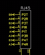
I notice there was some talk about inverted clock signals and their effect on locking in one of the threads. Are the "A" connections or the "B" connections inverted polarity? Im working with a third party designing an audio bridge and the LVDS driver is being adapted from an HDMI connection and I want to insure complete compatibility with the Teleport receivers.
RJ45 connection:
1-B0-bit clock (+) or (-)?
2-A0-bit clock (+) or (-)?
3-B2-Data (+) or (-)?
4-B1-Word Clock (+) or (-)?
5-A1-Word Clock (+) or (-)?
6-A2-Data (+) or (-)?
7-B3-Master Clock (+) or (-)?
8-A3-Master Clock (+) or (-)?
RJ45 connection:
1-B0-bit clock (+) or (-)?
2-A0-bit clock (+) or (-)?
3-B2-Data (+) or (-)?
4-B1-Word Clock (+) or (-)?
5-A1-Word Clock (+) or (-)?
6-A2-Data (+) or (-)?
7-B3-Master Clock (+) or (-)?
8-A3-Master Clock (+) or (-)?
No sure what talk you are referring to (maybe cronus/hermes? In that case all we are doing is shifting the time domain for the benefit of the FF - in the end the signals are all the same phase) - but in any case I would not apply such a inversion here - the signals are already optimized for least cross-talk - and I would not suggest any changes in that regard.
I believe it had something to do with the left right word clock and something else about inverting the polarity of the master clock to help things lock up better with certain hardware.
In any case lets ask it another way. If I am going to tap LVDS signals from an HDMI output connection instead of using a teleporter for the transmit side, I want to insure that I don't mix up the positive polarity signal with the inverted half of the differential signal. I assume but would like to verify that the A0,A1,A2,A3 LVDS pads are all positive polarity after reception and conversion back into I2s. The B0,B1,B2,and B3 are carrying the inverted signals. It is precisely because you have it right that I don't want to mess it up.
In any case lets ask it another way. If I am going to tap LVDS signals from an HDMI output connection instead of using a teleporter for the transmit side, I want to insure that I don't mix up the positive polarity signal with the inverted half of the differential signal. I assume but would like to verify that the A0,A1,A2,A3 LVDS pads are all positive polarity after reception and conversion back into I2s. The B0,B1,B2,and B3 are carrying the inverted signals. It is precisely because you have it right that I don't want to mess it up.
Ok sorry - I think I read your question too quickly!
Ax is non-inverted input/output for x
Bx is inverted input/output for x
Cheers!
Russ
Ax is non-inverted input/output for x
Bx is inverted input/output for x
Cheers!
Russ
The mapping of channels to signals (MCK/BCK/LRCK/Data etc....) is completely arbitrary. Any mapping is acceptable as long as it is the same on both ends 🙂
Cheers!
Russ
Cheers!
Russ
- Home
- More Vendors...
- Twisted Pear
- Introducing the bit "Teleporter"