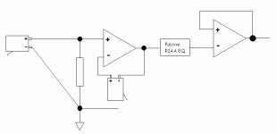
Something like the attached?
As i offered previously... i can come up with a working Grado + one the same with no stylus, if we can figure out how this works and if someone wants to build it.
The RIAA could also be feedback around the 2nd stage (don't know how you'd make it work with a single stage)
dave
As i offered previously... i can come up with a working Grado + one the same with no stylus, if we can figure out how this works and if someone wants to build it.
The RIAA could also be feedback around the 2nd stage (don't know how you'd make it work with a single stage)
dave
Attachments
Dave, that is not enough, you need th 47 k resistor to ground also in the feedback loop. Then it is exaclty the same as one of the solutions I came up with too. The other is to make an inverting amp. However, in both cases, we are limited to a gain of 1, and I cannot figure out how or if it is possible to get a higher gain and still have "perfect" compensation.
Christer said:that is not enough, you need th 47 k resistor to ground also in the feedback loop.
I'm out of my depth, but i'll keep growing the drawing.
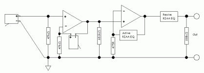
More like this?
I'm using Thorsten's El Cheapo Phono as a reference.
dave
Attachments
Dave,
No, it wont work. That is, it will work, but it won't give you the cancelling effect we want. Having som impedance in the feedback path for a unity-gain follower only affects the bias currents. Maybe it might have som slight effect on distorsion, but that was not what was intended anyway.
Just use the standard feedback theory for op amps. Let Z be the impedance of the cartridge and let R be a 47 K resistance. The cartridge can be viewed as a voltage source with inner impedance Z. I don't think a cartridge without load works quite as as intended, but for the lack of anything better, consider it as a voltage source outputting the signal v and with inner impedance Z. Z and R forms a voltage divider, so we get v1 = R/(Z+R) at the positive input. You circiut will have a gain of 1 for all frequencies (well, for the audio band at least) so we get v1 also at the output. It doesn't matter much that you have some reactance in the feedback here since it is a unity gain follower.
If you instead use the cartridge as feedback resistor (from output to -in) and a second 47 k resistor as gain resistor (from -in to ground) you get an amplifier with gain (Z+R)/R. The input signal was v1 = v*R/(Z+R) so we get the output signal v2 = ((Z+R)/R) * v1 = ((Z+R)/R)*(R/(Z+R))*v = v, and voila, we don't have any gain, but we have cancelled the frequencey dependent effects of the voltage divider formed by the cartridge and input resistor. Very elegant, but it only works for unity gain.
I am too lazy to draw a picture. Hope you get it from my text.
planet10 said:This what you mean?
Yeah. Oh, and those who think they can hear the directionaluty of an impedance may wish to swap the + and - terminals of the cartrdige in the feedback loop. 🙂
I think it might also be wise to put a small cap in parallel with the cartridge to close the feedback loop better at high frequencues (well above the audio range) to avoid oscillations, but maybe that introduces a new risk for oscillations, due to the inductivity of the cartridge?
Edit: A resistor in series with that extra bypassing cap would probably be a good idea to avoid oscillations.
mm compensation amplifier
I have somewhere the description and layout of a Riaa amplifier that compensates for the frequency non linearity as well as the mechanical resonance of a MM element.
It was published in the late 70's in a dutch electronics magazine and was backed up by the proper calculations.
All you had to do to adjust it to youre cartridge was to insert the proper R's and C's according to the impedance of the coil and cable/amplifier used.
It also corrected the RIAA curve to 0.5dB.
According to listening tests it worked quite well.When i have the time i am planning to build one myself.
Kro5998
It seems that this works in a similar fasion as the aleph X. I think that this has potential if someone could figgure out how to do it.
I use a pair of Y connectors for right and left phono cables to the phono preamp. Then I hook the spare cartridge in parallel, red to red, white to white, blue to blue, and purple to purple wires. The sound got richer and more like my Denon 103R. I use 2 Shure V15 type V cartridges. The shure alone sound thin and less body than the combined. I just use the second cartridge for cartridge loading. I still have the 49K resitor inside my SFP-1 phono stage. I tried to reversed the polarities on the second cartridge and noticed no sonic improvement.
Sorry to dampen the firework, but the reason that MM cartridge manufacturers specify a particular resistive and capacitive loading is that they require a non-flat electrical response to compensate for the falling mechanical response.
Broadly speaking, an MM cartridge is an inductor, so the first stage of that last circuit will have a response that rises with frequency. It might even oscillate. Why would you want to do that?
Broadly speaking, an MM cartridge is an inductor, so the first stage of that last circuit will have a response that rises with frequency. It might even oscillate. Why would you want to do that?
- Status
- Not open for further replies.
- Home
- Source & Line
- Analogue Source
- Interesting idea to make MM carts sound better...


