till said:
You are right.
And this was topic of the thread.
But as i´m not one of those DINKs mentioned earlier, 60€ is nothing i can spend every day. Most books mentioned in this thread are way to expensive. May book-groupbuys be the future?
I remember it was YOU who mentioned the DINKS. A fine example of self-referencing.
Now playing: Francis Cabrel: "Samedi soire sur la terre"
Jan Didden

Not enough books! However, you CAN go on the internet and get essentially the same equations. It is not as easy as some inputs, BECAUSE THD is NOT what you want, you need to know the change of magnitude of individual harmonic distortion components with changes of level. I am pretty sure the 'Radiotron Designers Handbook' has these equations as well.
john curl said:[snip] I am pretty sure the 'Radiotron Designers Handbook' has these equations as well.
I have that. This better be good...
Jan Didden
'Radiotron Designers Handbook'
Ha I got that one too... love it...sooo many pages... I won't ever get bored in this life....
Hi Jan,
Let me see if I can clarify this. Let's simplify things and assume that our nonlinear circuit has infinite bandwidth, so that the output is some simple nonlinear function of the input. If this function is smooth, without discontinuities, we can write the relationship between input and output with a Taylor series expansion. Let's also assume there's no DC offset, so the output is zero if the input is zero. The Taylor series expansion looks like:
[1] vout = a1*vin + a2*vin2 + a3*vin3 + ...
We'll ignore terms with powers higher than 3. Now our input is a sine wave, of the form:
[2] vin(t) = V*cos(omega*t)
We'll simplify the notation by letting omega * t = x, so that terms involving x will be the fundamental frequency, 2x will be the second harmonic, 3x will be the third harmonic, and so forth. So we have:
[3] vin = V*cos(x)
We need to substitute this in to the right side of our Taylor series expansion in (1). So what we really need are formulas that express cos2(x) and cos3(x) in terms of harmonics rather than squared and cubed terms. There's an important trig identity we can use that says:
[4] cos(a)*cos(b) = 1/2 * (cos(a+b) + cos(a-b))
Also cos(x) is an even function, so cos(-x) = cos(x) (that's why I'm using cos instead of sin). Also cos(0) = 1. Applying all this and setting a = b = x in equation (4), we have:
[5] cos2(x) = 1/2 * (1 + cos(2x))
Now we have the squared term in terms of the second harmonic (and a DC distortion term). To get the cubed term, we multiply the squared term in (5) by cos(x) again and apply equation (4) to the result. After some algebra, we get:
[6] cos3(x) = 3/4 * cos(x) + 1/4 * cos(3x)
So the cubed term gives a distortion term at the fundamental (compression), plus a third hamonic. I won't do all the math of plugging this in to the Taylor series expansion, because it will get messy. But I think you'll be able to see the pattern now. If we neglect the fundamental distortion (compression) term due to the third harmonic, the output will have a fundamental term with amplitude proportional to the input amplitude, a second harmonic term with amplitude proportional to the square of the input amplitude, and a third harmonic term with amplitude proportional to the cube of the input amplitude. If we take the ratio of the second harmonic amplitude to the fundamental, that's proportional to the input amplitude. If we take the ratio of the third harmonic amplitude to the fundamental, that's proportional to the square of the input amplitude.
So what John is saying is this. Take two circuits with the same distortion at, say, 2 Volts output. If we keep cranking up the input signal to get more and more output, the third harmonic distortion (ratio of third harmonic to fundamental) will grow as the square of the input amplitude. It will get ugly fast.
Dealing with more complicated distortion (say, distortion that depends on frequency) requires moving from a Taylor series expansion to a Volterra series expansion. The math for that gets pretty nasty, but if you're interested, there's some links to some Volterra articles at:
http://lanoswww.epfl.ch/studinfo/courses/cours_nonlinear_de/material.htm
Still, listening from the first watt to 10W, I would suspect that the open loop design would be superior, as the distortion would be only .02-.2% or so.
Make your foward path as linear as possible, and with as few singularities as possible, and then apply as much major loop feedback as you can get away with, without neccesitating the use of heavy (slew-rate sapping) compensation.
Tubes are very linear device. Are these making SET amp sound good?
Is there anyway to make transistors works linear without local feedback?
Thanks Andy C. Of course that is what I am trying to communicate. The main thing to remember is that IF you can measure 3rd harmonic at some level, you can extrapolate the amount of 3rd harmonic as the square of the level at either a higher or lower level, just like you can with analog magnetic tape. 2nd harmonic is different, in that it changes linearly with level.
This is why, so far, I have avoided making a 'global feedback' free power amp.
This is why, so far, I have avoided making a 'global feedback' free power amp.
andy_c said:Hi Jan,
Let me see if I can clarify this.
Andy,
You beat me to it. The advantage of time shift. 🙁
OK, here’s what I found. Source: Dennis L Feucht, Handbook of Analog Circuit Design, chapter 9, Precision Amplification.
I’ll describe the issue, and then add the three pages concerned in the following posts.
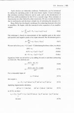
On page 425 a general expression for a series of harmonics is given (9.66) (from Bruce Hofer, one of the founders of Audio Precision. A man often underestimated). The equation simply says that there can be many component each with their own level (the a-term) which can be anything including zero. If zero, that component is not there. If only a1 is non-zero, it is a pure sine wave without distortion. (assuming v1 is a sine wave).
What then is done is measuring the amp gain at the zero crossing (A0), at max amplitude (A(V))and at min amplitude (A(-V)). In principle, this gives complete info on the THD. This is then fed back into the original equation and an expression is developed for the distortion using the measured values of the gain at zero-crossing, min and max signal. Looks very intimidating, but if you look at it hard you’ll see it is all only elementary algebra and trig.
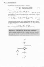
Now to page 426. There we find the found expressions for HD2 and HD3, in terms of the measured gain at the three points mentioned before. Of significance here is the fact that the 2nd HD changes linearly with signal (k.a2), but the 3rd HD changes with the square of the signal increase ratio (K^2. a3). That in fact is what John C alluded to.
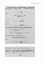
Further down that page an example is shown to put it in perspective, with a BJT CE amp stage. Go to page 427:
Page 427, the gain at zero-crossing is calculated: Ie = 1mA, and the gain is -9.52. Now we go to max signal by increasing Vi by 10mV, and min signal by decreasing Vi by 10mV. This changes Ie, and thus re (which, as can be seen in the gain equation at the top, is of course the cause of the distortion). The gain respectively becomes -9.68 and -9.38. Plugging the gain values into the previously found equations gives the % of 2nd and 3rd HD. Finally, the same calculation is done with a Vi change of +/- 25mV, and it can be seen that the 2nd HD changes linearly and 3rd HD changes by the square, as was found on page 426.
Well! That was fun, wasn’t it? What is the conclusion we can pull from this:
1 – You can indeed calculate distortion from inspection of zero-crossing, max and min amplitudes on a scope, although with very low THD I suspect it will get difficult and inaccurate;
2 – In a given amplifier with a given non-linearity, doubling the signal amplitude doubles the 2nd harmonic, but quadruples the 3rd harmonic! (You get even worse figures for higher order harmonics, I would suspect). That means that the THD spectrum of such a stage changes dynamically with the signal level. It’s like having a different amp at each signal level!
3 – John C related this to the amp gain, stating that at a gain of 28, the distortion of the input signal would be the square (784 times). It seems he makes the fundamental error of mixing up the incremental gain changes due to non-linearity, and which are responsible for the described effects, with the static mid-signal gain of 28. If that mid-band gain varied with max and min signal level between, say, 27.3 and 28.6 at a 1V input level, you can use these values to calculate 2nd (0.58%) and 3rd (0.015%) HD , and THEN say that if you increase Vi to say 2V, the 2nd will double to 1.12% and the 3rd will quadruple to 0.059%.
Jan Didden
Attachments
john curl said:Thanks Andy C. Of course that is what I am trying to communicate. The main thing to remember is that IF you can measure 3rd harmonic at some level, you can extrapolate the amount of 3rd harmonic as the square of the level at either a higher or lower level, just like you can with analog magnetic tape. 2nd harmonic is different, in that it changes linearly with level.
This is why, so far, I have avoided making a 'global feedback' free power amp.
John,
Having digested all that including Andy's clarification, do I now understand that this 'law' of linear 2nd and quad 3rd increase doesn't apply to feedback amps? I thought that it was valid for ANY amp with a given HD.
Or maybe you mean that because of this, we want to start out with as low HD as possible and that is difficult with low or no feedback? I can relate to that.
Jan Didden
... but it has! Both John and me have been quoting (from) books liberally.
I have been thinking some more (I know, surprise, but hey, that's life).
That remark from John about this quad power rise in 3rd harmonic really was an eyeopener for me, thanks John.
Next question: how can we design amplifiers that have a constant HD ratio across the input/output voltage range. Is it possible at all to design such a beast or are we up against a kind of unbending law?
Jan Didden
That remark from John about this quad power rise in 3rd harmonic really was an eyeopener for me
Jan, are you kidding? Don't disappoint us.
dimitri said:
Jan, are you kidding? Don't disappoint us.
I'm sorry Dimitri, I never realised it. 🙁 In hindsight, I THINK I read about it many moons ago, but apparently it didn't register. I find some consolation in the fact that John didn't get it quite right either😀
Ahh, all those uncharted paths! I need another couple of life's! Had another flying lesson today, getting real close to solo now, I feel it (and my instructor said it). I'm quite exited, but also a bit worried when the time comes he gets out and tells me to take her up for a spin. Man, what if he trusts me more than I trust myself??
Jan Didden
I'm glad that we have some of this settled. ;-) Now, the REAL multiplier is 800. This is because of THX and its insistence that .1V in = 1W out. You can do the rest of the math.
Next, back to what I was originally saying: IF you have a driver stage running open loop with, let's say: 1V out = .01% 3'rd harmonic distortion, THEN the power amp, made with EXACTLY the same driver stage, BUT with an added output stage (presumed 0% distortion contribution) will be adding 800 times more distortion than the preamp to the final distortion. This is because of the difference in output voltage between the preamp and the power amp at any one instant. It isn't very practical to have such a difference between the preamp and the power amp contribution, especially for high power, home theater designed amplifiers. Maybe you can get away doing this with a 10W amp, but not a 400W one. That is why I use global negative feedback in my 50-400W power amp designs. Now, Charles Hansen and Nelson Pass have made amps that have little or no global feedback and their measured specs show what happens, no matter what they do, or how hot they run. Still, at normal listening levels, zero global feedback would be preferred, all else being equal.
To keep this thread 'legal' I might mention that this difference between second and third harmonic level changes was learned by me in class and in textbooks as well. With experience in using conventional test equipment, this is obvious, BECAUSE the gain settings on conventional test equipment change voltage in 10dB steps. SO, if I have an amp (or preamp) at one output setting, and I click the oscillator gain switch 1 position (10dB), then I see 10 times as much distortion, if it is primarily third harmonic in content and most of my designs are that way. It becames second nature, after awhile and that is why I kept repeating myself----because I couldn't determine what I had stated was at issue.
I doubt that you can get away from this formula in a class A system.
john curl said:I'm glad that we have some of this settled. ;-) [snip]
Some of it, yes.
[snip]Now, the REAL multiplier is 800. This is because of THX and its insistence that .1V in = 1W out. You can do the rest of the math.
Next, back to what I was originally saying: IF you have a driver stage running open loop with, let's say: 1V out = .01% 3'rd harmonic distortion, THEN the power amp, made with EXACTLY the same driver stage, BUT with an added output stage (presumed 0% distortion contribution) will be adding 800 times more distortion than the preamp to the final distortion. [snip]
Not true John. The exact miltiplier you mentioned is 28 square = 784. But that is a moot point anyway because this doesn't enter the equation.
If you power amp has effectively (what you are saying) 0.01% 3rd THD, that's it. The input signal from the preamp has 0.01% (as you say) so the output of the power amp has THAT signal 0.01% distorted: 0.01% 3rd of the original carrier, plus the 0.01% of the preamp output signal again distorted 0.01% 3rd giving [very low] 9th. Where's the 800 or 784 coming in?
Jan Didden
Wait! John, I think I got you.
You refer to the previous part of the discussion where we said that if you have a certain THD, and you double the level, you quadruple the THD (3rd that is). But that is within a specific amplifier, no? Now we are going to amplify a signal with ANOTHER amp, doesn't that mean we start with a clean slate? I mean, 8% 3rd HD is unreal!
Jan Didden
Jan, just take the problem in reverse. Let's assume that we did manage to make a power amp that had, say, .01% third harmonic distortion at the high output level. What would it be at an output voltage that's 1/28 of this? It would be .00001276%. In other words, astonishingly low. Lower than we know how to make it.
And here's something else to consider. If these formulas are really correct under all circumstances (they aren't, they're only valid in the "weakly nonlinear" region) how do you explain that some power amps have more distortion at lower power levels than at higher?
And here's something else to consider. If these formulas are really correct under all circumstances (they aren't, they're only valid in the "weakly nonlinear" region) how do you explain that some power amps have more distortion at lower power levels than at higher?
- Status
- Not open for further replies.
- Home
- Amplifiers
- Solid State
- Interesting books....