Hi, I really need some guidance,
I'm trying to ascertain whether it is possible to add a low frequency boost below ~250Hz within the negative feedback loop of the Cyrus Two. (Cyrus One has an identical feedback circuit.)
Cyrus One Schematic.
I've tried to simulate the changing of each component within the loop and have also tried some practical experiments with croc clips and resistors. I stopped shortly after I added a 2u2 cap across R71 and heard some expensive sounding pulses about once every second. Ouch! I wish it was as simple as letting more bass through to ground by lowering R65 but I guess not. It is obviously a delicate balancing act even before I consider the wider implications of any alterations I make to the NFB. (Way over my head.) I'm saving up so that I can hire Bob Cordell. 😉
I'm looking for more bass overall even if it's only below 100Hz. 3 - 6dB would be great. I'll take what I can get within reason. My speakers are more than capable and the amp is powered by a beefy external power 500VA 84,000uF supply. I have built my own line level Baffle step/ bass boost circuit but I lose some transparency when I use it. (not just due to reduced H.F.)
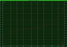
The attached graph shows the simulated frequency curve for the original NFB. Sorry about the bad quality due to compression. I'll try to fix that if I can.
Any help or advice would be gratefully received. The lack of LF content is the last major hurdle to overcome before I can actually Say that I have a great system. 😀
Many Thanks,
Martin. 🙂
I'm trying to ascertain whether it is possible to add a low frequency boost below ~250Hz within the negative feedback loop of the Cyrus Two. (Cyrus One has an identical feedback circuit.)
Cyrus One Schematic.
I've tried to simulate the changing of each component within the loop and have also tried some practical experiments with croc clips and resistors. I stopped shortly after I added a 2u2 cap across R71 and heard some expensive sounding pulses about once every second. Ouch! I wish it was as simple as letting more bass through to ground by lowering R65 but I guess not. It is obviously a delicate balancing act even before I consider the wider implications of any alterations I make to the NFB. (Way over my head.) I'm saving up so that I can hire Bob Cordell. 😉
I'm looking for more bass overall even if it's only below 100Hz. 3 - 6dB would be great. I'll take what I can get within reason. My speakers are more than capable and the amp is powered by a beefy external power 500VA 84,000uF supply. I have built my own line level Baffle step/ bass boost circuit but I lose some transparency when I use it. (not just due to reduced H.F.)
The attached graph shows the simulated frequency curve for the original NFB. Sorry about the bad quality due to compression. I'll try to fix that if I can.
Any help or advice would be gratefully received. The lack of LF content is the last major hurdle to overcome before I can actually Say that I have a great system. 😀
Many Thanks,
Martin. 🙂
Attachments
Martin
My advice would be to leave the feedback network well alone otherwise you run the risk of jeorpardizing the stability margins.
I replaced the LR network for BSC on my Jordan drive units with an RC network at the input of a Cyrus 1. A series resistor in the signal line followed by a capacitor and series resitor to ground gives a shelved response whereby the bass frequencies can be 6dB higher than the upper frequencies and the turn-over frequency can be selected to suit.
There are two existing series resistors in the Cyrus that can be used, R45 and R49 (both 4k7) so you only need to add a capacitor+resistor to ground after one of these (ie in parallel with C29 or C33). The load impedance following R45 is variable due to the presence of the volume and balance controls which will affect the filter operation to a certain extent so the better position is after R49.
Set up your simultor with a 4k7 series resistor followed by a capacitor+resistor to ground then a 75k load resistor and adjust the RC values to ground until you get the response you require. Try 100nF+4k7 as a starting point. As this is outside the feedback loop stability will not be affected.
Geoff
Thanks Geoff for the comprehensive reply. I suppose I knew that messing around with the feedback wasn't the most sensible idea with my limited knowledge. I had hoped to increase the overall feedback slightly while LF feedback stays the same and hopefully maintain stability but, to be honest, I was flying blind!! The sim results didn't seem to correspond to the actual effects of changing resistor values.
I'll start experimenting tonight and report back. I know someone else has a similar problem with an almost identical setup to mine. Should be interesting.
I also want to thank you for taking the taking the time to draw the schematic for the Cyrus one and posting it on your site. It has been so very useful to me over the past few years, especially since it is so well laid out and easy to read. Thanks also for doing the layout and revised schematic for the Cyrus One project thread. I hope that I'll be able to build my own one day.
Thanks again,
Martin.🙂
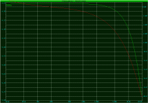
OK .... I then went on to try a 1uF capacitor with a 5K resistor. This gave quite an interesting effect that was very far from musical but made me will the bass guitar to go lower. 😀
It gave the impression that the bass player was just teasing and dancing around the higher notes until ..... Booom.....
I was thinking that more subtle version of this curve may be useful to overcome the natural rolloff of any speakers below ~50Hz.
I was wrong but it did make me feel like my speakers were 'ported' for a while. 🙂
Attachments
Hey Sonus,
Nice idea. I do a similar shelving LPF in my preamp for my open baffle speakers. About 6dB boost with a corner frequency of 120Hz.
The LPF is built around an opamp in the feedback loop like you wanted to do in your amp.. Trying to get a tube version (12B4A) going next.
I like Geoff's idea, gotta try it myself. 🙂
BTW, I was going to tell you to save your graphs as GIFs, but you beat me to it! See how much better they look? Smaller files, too. GIF is perfect for stuff like that.
Hi Panomaniac, I just discovered the GIF thing by accident but thanks for thinking of me.
Like you, I have made my own opamp baffle step but I haven't quite got it to be transparent yet with OP275GP opamps.
I'm just learning low voltage tube circuits at the moment so that will be my next move I think. I'll post my results on that at a later date.
My conclusion so far:
I haven't finished my experiments with this idea yet and I have learned a great deal from doing this so far.
I will aim to get the frequency response right but I don't think that I can make this a permanent fixture. Anytime that I try these things out in practise I lose some of the 'magic'. I know it sounds strange but my system is magical. 😉
The Cyrus amps always seem to forcibly eject the sound from the speakers and do so with a great deal of detail. I've even heard this when partnered with very cheap speakers.
The Tannoy dual concentrics add further to this and throw the sound 'out' still further into the room but I would prefer just a little more bass.
With the cap and resistor added, the life is removed form the mid and treble. It's hard to explain but it's as if everything becomes smeared somehow but I'm not sure why.
I wonder if the dual concentrics are very telling of phase shifts or perhaps it's because they are a 2.5 way system with the mid and bass being handled by the same driver (with another driver joining in below ~250Hz).
The Cyrus amps were always known for being a little forward and I always, until now, assumed that was because it was the British sound of that time or maybe optimised for vinyl. It seems to me as if they made a compromise to get the best they could out of the design.
I now have a new found respect for the designer and can see that it is a fine line between a great sound and a good one but maybe if I keep trying .......
- Status
- Not open for further replies.
- Home
- Amplifiers
- Solid State
- Integrating Baffle step into Cyrus 2 feedback circuit.