I have seen it said many times that insulating ESL stators results in decreased sensitivity of the ESL. I have also seen some comments about different insulating materials. I have never seen where that information came from, so I decided to perform some analysis to try to get an idea of the magnitude of the change that insulating the stators will produce.
I have written a short report on the calculation technique and an excel spreadsheet that allows you to calculate the effect of adding insulation to ESL stators. The result is expressed in terms of the magnitude of the electric field in the air gap of the speaker.
The spreadsheet allows you to enter the insulating material, its dielectric constant, and thickness, so you can compare the effect of different materials.
If you are familiar enough with Excel to use the goal seek function, you can enter the desired E-Field magnitude and back calculate to the air gap that will provide it. That way you can design an insulated driver to match the sensitivity of an uninsulated driver.
You can find the files here:
Report
Spreadsheet
I_F
Mark,
Some good effort put in here! You document your ideas exceedingly well.
I do have some comments after reading your report and trying your spreadsheet. I hope you will accept my comments in the spirit of wanting to be constructive and engaging in a free discourse where we all learn from each other. Initially I was surprised to see an argument about DC bias voltages levels using only capacitive analysis, but I wanted to see if you had a new angle. I followed the logic in your report until I came to the top of the last page where you said: “Each capacitor stores 6.092 uC, so…”. That’s where I hit a snag.
Let’s digress and try a thought experiment. I have two perfect capacitors, one is 24.4nF, and the other is 2.2nF, just to match your example. It doesn’t matter what the dielectrics are for this experiment. Assume there are no leakage paths. I momentarily connect each cap to an adjustable DC power supply to apply charges to each cap separately. I charge the 2.2nF cap to 2900 V DC and the 24.4nF cap to 100V, just arbitrarily. I know that I just induced a charge of 6.38uC on the smaller cap, and 2.44uC in the larger cap. I now connect the positive end of one cap to the negative end of the other, while leaving the outer leads of the caps open, unconnected to anything. I measure the voltage across these outer leads and see, as expected, 3000V. While the caps remain connected one-lead-to-one-lead, I measure the voltage across each cap and I still see 2900 V on the 2.2nF cap and 100 V across the 24.4nF cap. I must see these same voltages because no current was ever allowed to flow into or out of either cap after giving them the initial charges. No current could have flowed since the outer leads of each cap were always kept open (floating). I know that I now have a 2nF equivalent cap from the two series caps. With 3000 volts across this equivalent cap I calculate that I have a charge available to me from the outer leads of 6uC. I remember that I imparted 6.38uC and 2.44uC on the caps individually. But wait…
Just for grins, let’s now apply a new DC voltage to each of these same two caps. This time we’ll pick 1500 V for each one. After charging, I again place the caps in series (positive to negative) leaving the outer leads open. Again I measure 3000V across the pair since I allowed no current to flow through either cap – it couldn’t have flowed with the open outer leads. I calculate the charge on the 24.4nF cap at 36.6uC and the charge on the smaller cap is now 3.3uC. But since I still have a 2nF equivalent capacitance with 3000V across the outer terminals, I must still have a charge available to me on the outer leads of 6uC, same as in the prior case. Hmm…
Finally, I separate the two caps but I don’t discharge them. There is still 1500V measured across each one, as before. I now reconnect one lead from each cap together, but this time I connect the two positive leads together, leaving the negative leads open. I measure the voltage across the outer leads and I read ZERO volts. Just to double-check, I measure each cap again and each reads 1500V, as expected with no current being allowed to flow. As before the larger cap must be storing 36.6nC of charge and the smaller must have a charge of 3.3uC. If I mounted these charged caps in this series connection in a black (insulated) box with only the outer open pair of leads coming out, and asked an innocent observer to tell me how much charge is on the cap inside the black box, he’d measure the voltage at ZERO and correctly conclude that there is ZERO charge – AVAILABLE TO HIM OUTSIDE THE BOX. He would never know that 1500V lurked within and that there were 36.6uC and 3.3uC stored within separate caps. He could happily use this black-box 2nF cap (the series equivalent value) for years in various applications and he’d never realize the inner voltages and charges which are hidden from him (remember we said ideal caps with no leakage paths forever).
So now let’s discharge the same two weary caps to zero voltage each. Let’s then connect them in series again. No voltage across the pair, no voltage across either individual cap. A fresh start. Now let’s apply 3000V DC from a power supply across the outer leads. Remove the supply and connect a voltmeter. We read, as expected, 3000V across the outer leads. But what voltages would we predict to be across each one of caps individually? Answer: We can’t predict; it’s INDETERMINATE.
Before we jump off a cliff in despair, let’s return to the real world. In the real world, there is no such thing as an ideal cap. Each cap will have some leakage resistance, even if that resistance is enormously high. It is those resistances that determine the DC voltage ratios across series caps.
I will give one more analogy. If you are familiar with the principle of duality, we can use an example of inductors. We can draw direct analogies between the case of series capacitors with voltages, and the case of paralleled inductors with currents. That’s duality. If I place two ideal inductors (DCR=zero) in parallel and I then force a 1A DC current through this paralleled pair (rather than a voltage as with the cap examples), how much current will flow in each individual inductor? Answer: We can’t know; it’s indeterminate. We need real-world DCRs to decide that argument for us, just like we need real world leakage resistances to settle things for series caps.
So we return to what intuition should have told us in the very beginning: in deciding DC voltage ratios (including the electric fields for biasing electrostatic speakers) we must ignore capacitance altogether (inductance too). For DC calculations, we have to use only resistance calculations.
We should return to Janszen’s and Strickland’s work (see image below if I was able to post it).
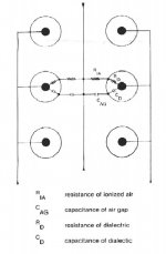
There is always going to be some leakage through an air gap. Air starts to ionize significantly above 1000V per millimeter, but there can be minute ion currents below this level too. This effect sets an equivalent resistance for air (Strickland labels it Ria). The insulation will have a resistance of between about 10^14 ohms-cm for PVC to above 10^17 ohms-cm for Teflon and PE (Strickland labels this Rd). Humidity matters in complex ways to both air ionization and hygroscopic effects in the plastic material, by the way. And never mind air pollution or salt content on the coast.
In any case, you have a simple two-resistor voltage divider between diaphragm and stator. It is very possible, under real world humidity levels and high bias conditions to have more resistance in the stator insulator than in the air gap itself. The voltage divider calculation predicts that the bias voltage, intended for the air gap, is instead stolen by the insulator’s larger resistance. With a 3000 V bias supply, you could end up with 300 volts across the air gap and 2700 volts “wasted” across the dielectric, in an extreme example. That makes for a very quiet ESL!
The dielectric constant is not directly relevant. If it were, using Mark’s spreadsheet and default example values, we’d predict only a 2.7% difference in bias voltages in the air gap between Teflon and PVC.
However, from a resistance perspective, PVC is roughly 1000 times leakier than Teflon. That’s why such a big difference in performance between these two insulators has been observed, in favor of the lower resistance PVC.
Again Mark, I appreciate the effort you must have put into your analysis, but I believe one wrong assumption about charges and their effect on DC voltages threw you off course. It happens to all of us. You've made so many other great contributions in this forum. If I’ve made a mistake here, I hope someone sets me straight. I’m here to learn and to share.
Some good effort put in here! You document your ideas exceedingly well.
I do have some comments after reading your report and trying your spreadsheet. I hope you will accept my comments in the spirit of wanting to be constructive and engaging in a free discourse where we all learn from each other. Initially I was surprised to see an argument about DC bias voltages levels using only capacitive analysis, but I wanted to see if you had a new angle. I followed the logic in your report until I came to the top of the last page where you said: “Each capacitor stores 6.092 uC, so…”. That’s where I hit a snag.
Let’s digress and try a thought experiment. I have two perfect capacitors, one is 24.4nF, and the other is 2.2nF, just to match your example. It doesn’t matter what the dielectrics are for this experiment. Assume there are no leakage paths. I momentarily connect each cap to an adjustable DC power supply to apply charges to each cap separately. I charge the 2.2nF cap to 2900 V DC and the 24.4nF cap to 100V, just arbitrarily. I know that I just induced a charge of 6.38uC on the smaller cap, and 2.44uC in the larger cap. I now connect the positive end of one cap to the negative end of the other, while leaving the outer leads of the caps open, unconnected to anything. I measure the voltage across these outer leads and see, as expected, 3000V. While the caps remain connected one-lead-to-one-lead, I measure the voltage across each cap and I still see 2900 V on the 2.2nF cap and 100 V across the 24.4nF cap. I must see these same voltages because no current was ever allowed to flow into or out of either cap after giving them the initial charges. No current could have flowed since the outer leads of each cap were always kept open (floating). I know that I now have a 2nF equivalent cap from the two series caps. With 3000 volts across this equivalent cap I calculate that I have a charge available to me from the outer leads of 6uC. I remember that I imparted 6.38uC and 2.44uC on the caps individually. But wait…
Just for grins, let’s now apply a new DC voltage to each of these same two caps. This time we’ll pick 1500 V for each one. After charging, I again place the caps in series (positive to negative) leaving the outer leads open. Again I measure 3000V across the pair since I allowed no current to flow through either cap – it couldn’t have flowed with the open outer leads. I calculate the charge on the 24.4nF cap at 36.6uC and the charge on the smaller cap is now 3.3uC. But since I still have a 2nF equivalent capacitance with 3000V across the outer terminals, I must still have a charge available to me on the outer leads of 6uC, same as in the prior case. Hmm…
Finally, I separate the two caps but I don’t discharge them. There is still 1500V measured across each one, as before. I now reconnect one lead from each cap together, but this time I connect the two positive leads together, leaving the negative leads open. I measure the voltage across the outer leads and I read ZERO volts. Just to double-check, I measure each cap again and each reads 1500V, as expected with no current being allowed to flow. As before the larger cap must be storing 36.6nC of charge and the smaller must have a charge of 3.3uC. If I mounted these charged caps in this series connection in a black (insulated) box with only the outer open pair of leads coming out, and asked an innocent observer to tell me how much charge is on the cap inside the black box, he’d measure the voltage at ZERO and correctly conclude that there is ZERO charge – AVAILABLE TO HIM OUTSIDE THE BOX. He would never know that 1500V lurked within and that there were 36.6uC and 3.3uC stored within separate caps. He could happily use this black-box 2nF cap (the series equivalent value) for years in various applications and he’d never realize the inner voltages and charges which are hidden from him (remember we said ideal caps with no leakage paths forever).
So now let’s discharge the same two weary caps to zero voltage each. Let’s then connect them in series again. No voltage across the pair, no voltage across either individual cap. A fresh start. Now let’s apply 3000V DC from a power supply across the outer leads. Remove the supply and connect a voltmeter. We read, as expected, 3000V across the outer leads. But what voltages would we predict to be across each one of caps individually? Answer: We can’t predict; it’s INDETERMINATE.
Before we jump off a cliff in despair, let’s return to the real world. In the real world, there is no such thing as an ideal cap. Each cap will have some leakage resistance, even if that resistance is enormously high. It is those resistances that determine the DC voltage ratios across series caps.
I will give one more analogy. If you are familiar with the principle of duality, we can use an example of inductors. We can draw direct analogies between the case of series capacitors with voltages, and the case of paralleled inductors with currents. That’s duality. If I place two ideal inductors (DCR=zero) in parallel and I then force a 1A DC current through this paralleled pair (rather than a voltage as with the cap examples), how much current will flow in each individual inductor? Answer: We can’t know; it’s indeterminate. We need real-world DCRs to decide that argument for us, just like we need real world leakage resistances to settle things for series caps.
So we return to what intuition should have told us in the very beginning: in deciding DC voltage ratios (including the electric fields for biasing electrostatic speakers) we must ignore capacitance altogether (inductance too). For DC calculations, we have to use only resistance calculations.
We should return to Janszen’s and Strickland’s work (see image below if I was able to post it).
There is always going to be some leakage through an air gap. Air starts to ionize significantly above 1000V per millimeter, but there can be minute ion currents below this level too. This effect sets an equivalent resistance for air (Strickland labels it Ria). The insulation will have a resistance of between about 10^14 ohms-cm for PVC to above 10^17 ohms-cm for Teflon and PE (Strickland labels this Rd). Humidity matters in complex ways to both air ionization and hygroscopic effects in the plastic material, by the way. And never mind air pollution or salt content on the coast.
In any case, you have a simple two-resistor voltage divider between diaphragm and stator. It is very possible, under real world humidity levels and high bias conditions to have more resistance in the stator insulator than in the air gap itself. The voltage divider calculation predicts that the bias voltage, intended for the air gap, is instead stolen by the insulator’s larger resistance. With a 3000 V bias supply, you could end up with 300 volts across the air gap and 2700 volts “wasted” across the dielectric, in an extreme example. That makes for a very quiet ESL!
The dielectric constant is not directly relevant. If it were, using Mark’s spreadsheet and default example values, we’d predict only a 2.7% difference in bias voltages in the air gap between Teflon and PVC.
However, from a resistance perspective, PVC is roughly 1000 times leakier than Teflon. That’s why such a big difference in performance between these two insulators has been observed, in favor of the lower resistance PVC.
Again Mark, I appreciate the effort you must have put into your analysis, but I believe one wrong assumption about charges and their effect on DC voltages threw you off course. It happens to all of us. You've made so many other great contributions in this forum. If I’ve made a mistake here, I hope someone sets me straight. I’m here to learn and to share.
Attachments
Brian,
Thanks for the comments.
I've been thinking about your post for a while and I think there is some confusion.
You are right that there is always leakage resistance associated with capacitors. In this case, the resistances will be through the air and through the bulk resistivity of the plastic dielectric, both of which will be very high values.
Those very high resistances values will determine the voltages across the two capacitors if you apply a DC voltage and ignore the time constants involved. The huge resistances combined with the relatively large capacitances will mean that the final voltage will be reached in time measured in minutes or hours, even for the smaller of the two capacitance values.
However, what my spreadsheet is intended to calculate is the more or less instantaneous voltage that appears across the capacitors when an ac signal (music) is applied to the speaker. It is the electric field set up by that ac voltage that drives the diaphragm. That voltage is changing so rapidly compared to the time constants of the leakage resistances and associated capacitances that the leakage resistances are effectively infinite.
I will make some changes to the document to better express what is being calculated.
As far as I know here is no reason why the voltage across two series connected capacitors would be indeterminate. Here are a couple links to some physics web sites that may provide some insight:
Davidson
another
and another
yet another
Do you have a copy of or a link to the papers by Jantzen and Strickland? I don't recall having seen them and I would like to see what they have to say.
The diagram you posted appears to relate the potential of the diaphragm to the leakage resistances through the air and the plastic dielectric. To me that diagram explains why the charge leaks off the diaphragm slowly, and why we need a constant or frequent connection to the bias supply to refresh the charge. If the resistance between the bias supply and the diaphragm is much lower than the leakage resistance to the stators, and the bias supply has a sufficiently low impedance of its own (i.e. is capable of supplying charge at least as fast as it leaks away), the leakage of charge from the diaphragm doesn't matter, as evidenced by so many working ESLs.
Thanks,
I_F
Hi Mark,
Yes, I did read into your paper that you were talking about establishing DC bias levels. You used a consistent example of V=3000 volts and showed a battery symbol for the voltage supply, an indicator of a DC supply. Sure, as soon as the voltage varies with time (becomes AC) the capacitors come into play as a capacitor divider, but not at DC. In the AC case (music), you can just use the capacitor voltage divider rule to see what fraction of the applied AC voltage stays across the insulator and how much goes across the air gap. VC1=Vtotal*C2/(C1+C2). I don’t think that any more complicated analysis of the capacitive/AC component is required. (You’d figure it using capacitance per unit area, of course and it gets a bit hairy figuring out round insulators, etc.)
This AC component has to be added or superimposed upon the existing DC field since the DC part is separately determined purely by resistive ratios.
Regarding the charge analysis for DC, it depends on initial conditions. Since any application of a “DC” voltage is really a momentary AC (such as step function), the capacitor divider rule would apply momentarily. If no residual charge remained in the insulators (although Strickland said that it can linger) - which is to say initial conditions are zero - you can use simple capacitive divider analysis. But the paralleled resistances would soon cause those charges to migrate according to the resistive voltage divider rules within a few seconds/minutes, and then after that the capacitor ratio now longer matters for the DC bias.
For AC signals (music), we really have to consider BOTH the resistors and capacitors in the series-parallel circuit shown above to correctly analyze the AC voltage in the gap. As I said earlier, the resistive part of the dividers can swamp the capacitive part under conditions of lower frequencies, high absolute DC voltages, high humidity and high-R insulators. At very high frequencies the capacitive divider will dominate (more current is flowing through the Cs than through the Rs), so there will be a frequency of transition from resistive-divider-dominated to capacitive-divider-dominated. This reminds me of compensating a scope probe divider, except the variables are less predictable and more prone to drift.
I have been using uninsulated stainless steel screen meshes in my experiments – these get around all of the voltage reduction problems and have no transition frequency, but offer no arc limiting either.
By the way, my old RTR ESL tweeters (great units) used a crusty looking coating on the wires, probably carbon, to avoid the problems that Strickland was alluding to and still provide some arc limiting.
The Strickland paper that you are probably referring to can be found on several sites (try Googling), but one is:
http://www.izzy-wizzy.com/audio/spkr.html
I would suggest that you look at Janszen's patents.
Hey, this has been fun and has made me think, and that’s a good thing as Martha used to say.
Brian,
If the time constant of the RC combination were 1/20 sec. (corresponding to 20 Hz), using the smaller of the two capacitances (about 2 nF), the leakage resistance would have to be down to 25 Mega Ohms. Under what sort of operating conditions (other than when the speaker is arcing!) would the leakage resistance ever get anywhere near that value?
Hmmmmm.
I_F
Maybe thinking about things in a different way will give more insight.
Consider that an electric field between two plates depends on the distance between them and the material separating them. So an insulator with greater permittivity behaves (in terms of electric field) like a greater width of air, so adding an insulator is similar to increasing the gap, thus reducing sensitivity (lower electric field)
Now a quick read of the Strickland paper suggests that the charge on the diaphragm (at least of the ESL he is describing) depends on a 'resistive' divider which includes the bias resistor (500Mohms in his case I believe), 'partially ionised' air and the 'insulators'. So changing the plate insulation in this case will effect the charge on the diaphragm also effecting sensitivity - If I am thinking this through correctly possibly in the oppisite way, a high resistance insulator might result in a greater charge on the diaphragm and greater sensitivity from this effect, which brings up the question of resistivity versus permittivity of various insulation choices.
two nitpicks - for perfect caps in series it is easy to calculate the voltage across each with when connected to a DC source - they both must have the same charge and so C1V1 = C2V2 - of course with leakage the resistances determine the voltages, so the leakage may well effect the diaphragm charge - and at AC (hopefully for audio freq) the capactance will determine the voltage and I_forgot analysis works - even though he did it at DC (I think - I did not look real close) and so you are both right!
Now the problem of dielectric absorption worries me a little - those insulators getting charged up and not letting go, my intuition tells me that this is probably a bigger problem at high voltages of ESLs than in caps at lower voltage and it is a problem there...
More to think about...
Edit - 2 nitpicks - well the first wasn't really one I guess, and second I completely forgot about - it was to do with the first link to capacitors and DC -
it showed electrons flowing to create charged caps and I think that the electron does not flow all the way from one cap to the other, but the electric field moves and an electron from the wire moves to the cap as a result - picky, picky, picky!
If the time constant of the RC combination were 1/20 sec. (corresponding to 20 Hz), using the smaller of the two capacitances (about 2 nF), the leakage resistance would have to be down to 25 Mega Ohms. Under what sort of operating conditions (other than when the speaker is arcing!) would the leakage resistance ever get anywhere near that value?
Good question. (By the way, a time constant of 1/20 second corresponds to a pole frequency of about 3.2Hz, not 20Hz, if I read your comment correctly. Don't forget that pesky 2pi term.) Anyway, of course your original assumption was for a full 1 sq. meter of area to arrive at the capacitance, and it’s a reasonable value (1000pF is sometimes thrown around as a generic ESL design bogey). I guess for that full scale assumption we’d have to consider the resistance of all those thin individual wire insulation sections in parallel, as well as the air gap resistance across a full 1 sq. meter, assuming some incipient low level of ionization. Either that or look at it on a per-square-centimeter basis with the effect of one or two stator wires and the 0.2 pF or so of capacitance in that small unit area. Either way should give you the same RC. I don’t know what it would be for a typical speaker (lots of assumptions and variables and tedious geometry calculations), but I’m assuming 1/(2piRC) generally would fall below the audio band, but under some circumstances it might not.
Now the problem of dielectric absorption worries me a little - those insulators getting charged up and not letting go, my intuition tells me that this is probably a bigger problem at high voltages of ESLs than in caps at lower voltage and it is a problem there...
Yes, it's not a problem you read about much in ESLs, is it? Strickland told me once that he'd seen lab speakers that actually played louder after power down of the bias supply than before (for a while anway), and sometimes he observed audio phase reversals at that time too. This was all with PE before he switched to nice leaky PVC. Weird science.
The problem with high surface resistivity insulation such as PE or teflon is due to the surface charge cloaking the stator AC signal voltage. Under no signal conditions the stator bias voltage appears on the surface of the insulation (facing the diaphragm) since no current flows. As the signal swings in the opposite direction the surface charge can not change with it instantaneously but must first be discharged through the insulation resistivity. Making the insulation thin will help some but ultimately it is a surface charge problem and lowering the resistivity is the fix.
Mike,
Glad to see another Beck interested in ESLs and posting here!
Yes, your point is well taken and it has been expressed in this thread and in others, although that original point may have gotten lost in all the other tangential comments. Strickland was absolutely right.
I think that just making a high-resistivity insulator like Teflon or PE thinner will hardly help, since their resistivities are about 1000 times greater than PVC to begin with. My posting from May 31 lists volume resistivities of a few potential insulator materials:
Insulator resistivities
BTW, bare naked stators have an appeal if safety and arcing can be addressed. That is where my ESL attention is focused right now, scarce time permitting. I am toying with alternate arc suppression ideas. Will report if and when I have something to share.
Fantastic thread!!!
Thanks to all for posting such thought provoking ideas. This is a great learning experience. A real melding of the minds and something wondeful will I am sure come out of the pot. Regards Moray James.
Thanks to all for posting such thought provoking ideas. This is a great learning experience. A real melding of the minds and something wondeful will I am sure come out of the pot. Regards Moray James.
Brian,
Likewise it's nice to see another Beck in the technical arena. We probably fell out of the same tree somewhere back in Germany?
Re: bare stators. The smooth wire stator works best as it has almost no fringing of the e field. And a larger diameter improves this as well. Any data on efficiency improvement pvc vs bare?
Mike

It's unusual to touch two stators simultaneously while music is playing loudly, but it COULD happen. Any uninsulated stator must be considered a potentially deadly object when the music is on or if you have a direct drive amp.
Even contacting one stator could be dangerous
Good point SY. I plan to ensure safety somehow if I ever get to a “final” configuration. Also, if any point in the secondary circuit, such as the center tap or one end of the bias supply, is grounded, and this is very typical, then one could be shocked (with music or test tones playing) by simultaneously contacting just one stator and also any grounded point such as a chassis. I’ve connected a high-voltage probe to my Quad ESL-63’s stators and have watched with amazement as thousands of volts of music danced on the display at normal sound levels.
As we've noted in prior threads on this topic, the secondary outputs/stators are perhaps as dangerous as, if not more dangerous than, the bias supply, which should have a large resistor is series with it. Besides ensuring constant charge operation, this resistor limits current in an accidental contact (but still not recommended!). The music voltages on the stator come from a relatively low source impedance and could push deadly current into flesh. Others disagreed on this point, unwisely I think.
Brian, You're quite right and it's just a matter of time before someone gets across the secondary winding. I always wondered how a well-known manufacturer gets away with only powder coating their stators, which are not enclosed behind any protective screening or even a grille cloth. I believe they must hi-pot test each stator to insure the insulation is good. I believe they run about .06 D/S spacing for 6kVpp max drive. Not too comforting!
Mike
Mike
This thread is older than the hills, but I ran across this information and found it useful. Perhaps someone else thinking about insulating ESL stators will find it useful as well.
While I'm at it, perhaps someone can let me know if I'm off base while narrowing my insulation choices. I'm about to order some wire for some insulated wire esl stators. Heavy build nylon seems like it might be a decent approximation to the PVC that Acoustat's Jim Strickland recommends. I can buy nylon insulated magnet wire for much less than pvc-coated single strand wire, and when you realize that it takes a mile of 24 gauge magnet wire (literally!) to build two 6 foot tall ESLs, the cost adds up! Does nylon have some nasty property I should know about before pulling out the charge card?
While I'm at it, perhaps someone can let me know if I'm off base while narrowing my insulation choices. I'm about to order some wire for some insulated wire esl stators. Heavy build nylon seems like it might be a decent approximation to the PVC that Acoustat's Jim Strickland recommends. I can buy nylon insulated magnet wire for much less than pvc-coated single strand wire, and when you realize that it takes a mile of 24 gauge magnet wire (literally!) to build two 6 foot tall ESLs, the cost adds up! Does nylon have some nasty property I should know about before pulling out the charge card?
I think that almost no glue will bond to nylon well , so you will have to encapsulate wires with glue. Thats not a big problem , though.
Nylon may be a little on the high side for resistivity. You can get polyester coated magnet wire. The problem is making it flat, ie it must be tensioned. It will change length with temperature so string it in a warm room. Try a test panel before you invest a lot of time and $$ to make sure it will be feasible.
Tensioning, and the structure that maintains flatness, are clearly the "tricks" to wire stators. Am I corrent in assuming, Mike, that your comments about tensioning and temperature dependence are meant to apply to wire stators in general, and not specifically to nylon insulated wires? I would think the copper's behavior would dominate that of the insulation.
Hello Few,
I was just pointing out the problems with temperature and materials. A 6 ft length of steel wire will grow about .009 inches with a 20F increase in temperature. A copper wire will grow .013 inches. This is not much but will have some effect on your stator and could make the wires droop. The insulation will expand and contract at 4 to 5 times this rate. You can calculate these values using the CTE (coefficient of thermal expansion). Go to matweb.com and find values for the material you want. For example, steel has a cte of 6 microinches per inch per degree F. For 6 feet and 20F change: L=(6E-6)x 72inx20F=0.013 inches.
Of course if you are building panels for yourself and they will always be kept in a controlled climate, then you needn't worry too much. Speakerbuilder magazine ran a wire stator project about 1991 called the Amber. It used eggcrate and pvc insulated wire. The eggcrate was bowed and the wires strung so that they were under tension. When assembled, the stators balanced forces and the result was a flat stator. The Audiocircuit has a factory photo tour showing the Acoustat construction method. The Amber project makes a few variations.
Hi,
Nylon-based coating is what ML uses for their stators.
Look for brand names like Rilsan or Corvel. Parameters like Epsilon and resistance is similar to PVC.
jauu
Calvin
Nylon-based coating is what ML uses for their stators.
Look for brand names like Rilsan or Corvel. Parameters like Epsilon and resistance is similar to PVC.
jauu
Calvin
- Status
- Not open for further replies.
- Home
- Loudspeakers
- Planars & Exotics
- Insulated vs. bare metal stators