Hi there!
First of all: I love this forum.
so much knowledge and something to read for aaaaaages. 😀
But i´m still struggeling with my instrumentation amp design, because i found no answer.
the amp should be used as the input stage in my fully balanced preamp.
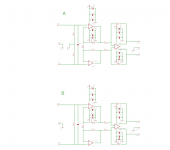
below i posted the schematic and i´m not sure which version i should use.
i would tend to version "B", because the whole signal path wouldn`t have any connection to ground inside the circuit. PIN1 of the XLR connector would go directly to the enclosure. and only two caps (HF-Filter directly under the XLR connector) would go from + and - via an bias caps to the enclosure.
So, in case of "B" the PIN1 Problem should be fixed anytime, right?
and i don`t have to think about using two double relays to switch the two signals and ground, because i only have to switch the two signals, right?
because in my case, when i would choose Version "A" it would be the only connection to ground in the whole circuit. neither the output stage has one, nor the volume attenuator.
which brings me to my next point.
for the volume attenuator i´m thinking about two options.
---a 6-8 relays switched ladder
---or a two stage relay switched shunt. one stage for the 10dB steps and the other for 1dB steps.
i´m really not sure. in one case i have several resistors and relays in the signal path, in the other i have only two series resistors BUT one more opamp.
what do you people think about that?
every help would be appreciated. 🙂
thanks
claas
First of all: I love this forum.
so much knowledge and something to read for aaaaaages. 😀
But i´m still struggeling with my instrumentation amp design, because i found no answer.
the amp should be used as the input stage in my fully balanced preamp.
below i posted the schematic and i´m not sure which version i should use.
i would tend to version "B", because the whole signal path wouldn`t have any connection to ground inside the circuit. PIN1 of the XLR connector would go directly to the enclosure. and only two caps (HF-Filter directly under the XLR connector) would go from + and - via an bias caps to the enclosure.
So, in case of "B" the PIN1 Problem should be fixed anytime, right?
and i don`t have to think about using two double relays to switch the two signals and ground, because i only have to switch the two signals, right?
because in my case, when i would choose Version "A" it would be the only connection to ground in the whole circuit. neither the output stage has one, nor the volume attenuator.
which brings me to my next point.
for the volume attenuator i´m thinking about two options.
---a 6-8 relays switched ladder
---or a two stage relay switched shunt. one stage for the 10dB steps and the other for 1dB steps.
i´m really not sure. in one case i have several resistors and relays in the signal path, in the other i have only two series resistors BUT one more opamp.
what do you people think about that?
every help would be appreciated. 🙂
thanks
claas