I have DAC with anode follower (voltage gain) tube output stage (2x 6N8S, 1/2 per channel). Now I want to install (other half of same 6N8S) a 2nd stage buffer (cathode follower) and potentiometer so I can directly drive tube power amp (with 6n6p at input). My question is where is a best solution to installi the potentiometer, either between the first and second stages or after the second stage?
Thanks.
Thanks.
Pot between follower and power amp (attachment written for B+ of 300V, pls scale depending on your supply).
If you fit the pot between gain stage and follower, you need 2 additional coupling caps and separate bias for the follower.
If this is a 2 channel stereo setup, I would put both gain stages in one tube and both followers in the other tube.
Because the followers have much higher voltages on their cathodes than the gain tubes.
Attachments

Unfortunately, a pot much larger than 10k will cause a high frequency roll off if unbuffered.
Also a bass roll off will happen from a small pot at the output due to the preceding coupling capacitor.
Tubes require a much higher value.
Better to connect the 10k pot just before the DAC output stage, and direct couple the two tube stages.
Also a bass roll off will happen from a small pot at the output due to the preceding coupling capacitor.
Tubes require a much higher value.
Better to connect the 10k pot just before the DAC output stage, and direct couple the two tube stages.
The OP did not say anything about a 10k pot.
The pot right at the input of the power amp is quite common, something like 100k ... 500k will do well. Proper size of cap assumed.
As shown in the.upper example of the attachment above.
This would also allow the power amp to be used with other sources.
The pot right at the input of the power amp is quite common, something like 100k ... 500k will do well. Proper size of cap assumed.
As shown in the.upper example of the attachment above.
This would also allow the power amp to be used with other sources.
Thanks.
Just to confirm, best solution will be to add one more CF stage after POT. Final diagram will look like this: DAC - AF - CF - POT - CF.
Just to confirm, best solution will be to add one more CF stage after POT. Final diagram will look like this: DAC - AF - CF - POT - CF.
When you say "anode follower" does this also mean that the anode follower provides the summing junction?
All good fortune,
Chris
All good fortune,
Chris
i would call that over engineering ...Thanks.
Just to confirm, best solution will be to add one more CF stage after POT. Final diagram will look like this: DAC - AF - CF - POT - CF.
If your power amp already has a volume pot in the 100k+ range, you may not even need any CF.
Unless you have to drive a long(er) cable between anode followe tube and power amp.
In which case one CF+ cap to drive the cable capacitance (plus amp input) can be beneficial.
Anyway, as Chris wrote, it may be helpful to know the details of
- Anode follower (schematic) to assess its drive capabilities
- cable (which and where)
- Amp input (schematic) to assess load
- should Amp be usable with other sources as well
-
Last edited:
Power amp will not be used for any other source, just for "tubeDAC". Interconnect cable from dac to power amp is 1m long. Thanks.
If I change pot to 10K and preceding coupling capacitor to 4uF or higher, will this dac + AF be able to feed power amp?
10k is best in preamp if you have a long cable.
20k is best in preamp with short cables.
Any higher value of pot should be inside the power amp.
20k is best in preamp with short cables.
Any higher value of pot should be inside the power amp.
6N8S is equivalent to US type 6SN7.
Looking at the schematic, 2,5V on the cathode means there's about 4.9mA plate current.
With those operating points, a degenerated 6SN7's typical rp is at least 10k ohms (probably a bit more). 6N8S should be the same or very similar.
A 7.5k ohm plate load is going to load down that 6N8S pretty heavily. Maybe that's OK with these low signal levels. You don't need much gain here, right?
A second consideration is that a pot on the output of the 6N8S should have a value of 10X the Zout of the 6N8S stage. I think a 100k ohm pot would be the minimum value for a volume control on the 6N8S output. 10k would load down the 6N8S even more heavily (10k in parallel with 7.5k).
The volume control should probably be put on the input of the power amp so that it doesn't have to drive long cables. Or you could put a cathode or source follower after the volume control, to drive interconnect cabling from DAC to power amp. Or drive the volume pot and interconnect cabling with a follower. At any rate, it looks like some impedance matching is asked for here.
My opinion, YMMV, you can disagree if you like, for sure.
I
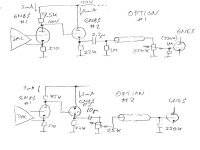
it seems that you have 2 options if you want to go for CF buffer:
who knows ... but its your decision ...
(see attachment)
probably not ...If I change pot to 10K and preceding coupling capacitor to 4uF or higher, will this dac + AF be able to feed power amp?
it seems that you have 2 options if you want to go for CF buffer:
- 250k pot at the end of cable at the power amp input
- 25K pot after the CF in front of the cable
who knows ... but its your decision ...
(see attachment)
Attachments
Last edited:
If I change pot to 10K and preceding coupling capacitor to 4uF or higher, will this dac + AF be able to feed power amp?
There's no problem feeding the power amp with any value of pot.
The cable capacitance is the issue for any pot over 20k.
I would use a 4uF coupling capacitor, a 20k pot in the preamp, and NO cathode follower, for the best sound.
But use short, low capacitance cables to the power amp.
In this case a 20k pot is better than a 10k pot, for lower distortion from the common cathode preamp stage.
My interpretation of the ES9018 data sheet:
https://www.mouser.com/datasheet/2/1082/ES9018S_Datasheet_v2_3-3074312.pdf see p.39 Application Diagrams
is that it requires an external summing junction. If that's correct it must be addressed first.
The term "anode follower" has an accepted meaning that resembles an inverting op-amp (which would make a good conventional summing junction) that doesn't apply to the circuit as proposed.
All good fortune,
Chris
Last edited:
Another option could be to use the cathode followers to bootstrap the load of the gain stage: it will have a flatter loadline, and a low output impedance, allowing to use lower value gain pots.A 7.5k ohm plate load is going to load down that 6N8S pretty heavily. Maybe that's OK with these low signal levels.
A second consideration is that a pot on the output of the 6N8S should have a value of 10X the Zout of the 6N8S stage.
- Home
- Amplifiers
- Tubes / Valves
- Installing the potentiometer at different points in tube output stage/preamplifier circuit