Hey All,
I have a Sony XA20-es, US version. It has a toslink, and I was wondering if it might be possible to make a digital out, RCA version - easily. I've taken this thing apart before and added an IEC power input, and added extra weights to the inside. I can solder, take some of the boards out, and am not afraid to go in depth with this, I'm just not sure what to do, and if it is even possible. Is this something where I can just splice some wires to a new RCA I can install to the back of the transport, or is it more complicated than that - something that should be left to someone with more experience?
Thanks,
jake
jsmccray said:
Is this something where I can just splice some wires to a new RCA I can install to the back of the transport, or is it more complicated than that - something that should be left to someone with more experience?
Hi, here's a variant I saved from a thread here. Based on the discussions there I'd say this is the best... take the signal from the input of the toslink piece inside and run it through this circuit.
Attachments
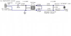
You need to be a bit carefull with the circuit posted above, the SAA7220 which it is designed for has a high current driver for this output. This output is desinged to drive the low impedance required for SPDIF 75R terminated signals. However the sony may not have this it might just be an ordinary digital ouput designed to drive a logic input (Such as is used on the input to a TOSLINK transmitter). If this is the case you could burn out the driver in the output of the sony chip.
I would buffer the signal with a 74HCU04 chip (or buffer chip of your choice) and split the 158R resistor into two resistors in parrallel (try to get a value as close to 316R as you can) using two of the HCU04 outputs. This will give you enough current drive without risk of buring out the SONY chip set.
Regards,
Andrew
Thanks guys!
Unfortunately, this is quite over my head 🙁
At least I know now - I'll send it to someone in town!
Best,
jake
Unfortunately, this is quite over my head 🙁
At least I know now - I'll send it to someone in town!
Best,
jake
This can be easy .......
The toslink out put should have three pins one is voltage, one dig signal and one dig ground ....
A quick and dirty method is to locate ground ...thats easy ....so you have a choice of the other two as dig sg. trace back each the dig sg will have no other connections and should go back to the chip. the voltage pin track will have all manner of other connections as it goes back to the psu including caps and resistors.
I've used this method on 5 or six units now with total sucsees....contact me if you need more info.
Excellent!
so are you saying that I can use the voltage as one of the inputs for the RCA, and the dig sig. as the other input of the RCA? I'm not sure if that is what you are saying, but I'm guessing at this point. I'd email you, but I'm still new so I'm under monderation at this point.
Thanks,
jake
so are you saying that I can use the voltage as one of the inputs for the RCA, and the dig sig. as the other input of the RCA? I'm not sure if that is what you are saying, but I'm guessing at this point. I'd email you, but I'm still new so I'm under monderation at this point.
Thanks,
jake
I use the attached circuit for my Denon CD player. I took the digital signal from the optical output. The 5V supply is also got from the optical output
I used the method of splicing from the Toslink outputs, and it has worked famously! No problem at all, I'm now going continue modding. Where in the US would you suggest I buy Schottky's and Os-Con caps, and the other things?
Thanks for everyone's help!
jake
Thanks for everyone's help!
jake
- Status
- Not open for further replies.
- Home
- Source & Line
- Digital Source
- Installing digital out - diy