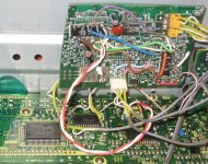
This player is a Sony CDP397. Inside is mostly empty space. It uses a CXD2500, which produces a set of signals similar but not exactly I2S, which is what the TDA1543 (the new DAC chip) expects. The main issue is that the LRCK signal changes state too early, by 8 sample bit clocks. The TDA1543 grabs the first 16 bits it sees when this LRCK changes state, and ignores any more bits that come along. Thing is, the CXD2500 runs a bit clock 24 cycles times the "word" length. Instead of 16 times the TDA1543 expected. The CXD2500 sends the MSB bit for teh first 8 clocks, then the rest of the bits. But the TDA1543 grabbed 8 bits of MSB and then the next top 8 bits of audio data, which made the sound very low, and would sound like 9 bit audio, yucky. To get around this I decided to build a delay circuit to make a new "WS" (thats what the TDA1543 calls the LRCK signal) off a counter counting out 7 cycles of sample clock, that in turn triggers a latch to grab the state of LRCK and assert it onto a new WS signal that then feeds the TDA1543. This in turn makes the TDA1543 grab all the audio bits correctly.
I didn't remove the old DAC chip (one of those noise shaping thingies) out of the player, it feeds the headphones, and it houses the master timing oscillator.
I haven't built the tube circuit just yet, as I need to round up a power supply for it. Now I'm feeding the DAC output to an audio amp for testing.
The hacked up board used to be a piece of a PC soundcard, one that used the TDA1543.
Attachments
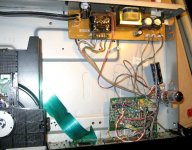
I built the tube buffer stage and its power supply. I used a 12AU7, and I changed the cathode resistor to a 10K. This may seem a little high, but realize that the grid has a DC bias of 2.4V as it's directly connected to the DAC chip's output. The B+ is, after a bridge rectifier and CRC filter (100uF - 3.9K - 100uF), 118VDC.

The power transformer is one of those with separate 120V primaries, so it could be used in 240V countries. This particular style has each primary on its own bobbin, which means there should be plenty of powerline hi-pot isolation between them. Here I used one as a secondary. But this cuts the power rating of this transformer in half. But it's only has a 2 watt heater on it, and a few ma off the B+ of 140V or so, so a total of 4 watts.
As this player has a "soft" button for power (and a remote control that I don't have), to make the tube shut down when I turn the player "off" I used a small relay to switch the tube power supply transformer, this relay powered off the switched 5V supply inside.
Attachments
Inserting DAC chip into cp player
The CX2500 can be directly connected to the TDA1545A DAC with no reclocking issues at all. You do not need to use CS841x chips or need to reclock anything! You tap off the three signals WDCK, LRCK and DATA from the CDX2500 and couple it into the TDA1545A. I followed the data sheet for the DAC and used the op amp I/V stage as per data sheet. I also used another op amp stage with 2x gain and a little roll off above 20Khz after the I/V stage. I used this and have incorporated it in my Sony CDP-990 cd player with no extensive hacking. I have both the existing dac and also the TDA1545A NOS dac hooked up from the CDX2500 and have outputed the NOS dac with its own set of RCA's at the back. Check out this old post http://www.diyaudio.com/forums/digital-source/127825-sony-cdx2500-tda1543-direct.html. If you want I can post the complete CCT. mod for this. Yhe most simple mod I have done without damaging the CD player.
The CX2500 can be directly connected to the TDA1545A DAC with no reclocking issues at all. You do not need to use CS841x chips or need to reclock anything! You tap off the three signals WDCK, LRCK and DATA from the CDX2500 and couple it into the TDA1545A. I followed the data sheet for the DAC and used the op amp I/V stage as per data sheet. I also used another op amp stage with 2x gain and a little roll off above 20Khz after the I/V stage. I used this and have incorporated it in my Sony CDP-990 cd player with no extensive hacking. I have both the existing dac and also the TDA1545A NOS dac hooked up from the CDX2500 and have outputed the NOS dac with its own set of RCA's at the back. Check out this old post http://www.diyaudio.com/forums/digital-source/127825-sony-cdx2500-tda1543-direct.html. If you want I can post the complete CCT. mod for this. Yhe most simple mod I have done without damaging the CD player.
The CX2500 can be directly connected to the TDA1545A DAC with no reclocking issues at all. You do not need to use CS841x chips or need to reclock anything! You tap off the three signals WDCK, LRCK and DATA from the CDX2500 and couple it into the TDA1545A.
You're right in that I did not reclock the audio bits, and I used the bit clock as is as well. The only signal I had to rework was the LRCK, to get the timing of it to match what the TDA1543 requires. Below it's the WS signal my circuit creates. I could have done that with a 74LS374 8 bit latch, but I didn't have one available but I did have the 74LS74 and 74LS163 chips.

Just thought if you wanted to use the TDS1545A instead of the TDA1543 for simplicity sake. You do not need to use any other logic chip to reclock the signals. Out of the CDX2500 pins 32, 34 and 35 straight into theTDA1545A pins 1, 2 & 3
cdx2500 TDA1545
pin34 to pin3
pin 32 to pin2
pin35 to pin1
I think that is how it goes. If I have made a mistake I will have to dig up my notes
cdx2500 TDA1545
pin34 to pin3
pin 32 to pin2
pin35 to pin1
I think that is how it goes. If I have made a mistake I will have to dig up my notes
I dont understand everything.... Were to take 12.1Mhz signal from? From cd player clock 16Mhz and reclock it? what is thata resistorsa on pin 1 and 10 on ls163 chip? is necessary to connect clk to 74ls74? Glue logic base on 74LS374 still need reclock ing to 12.1 . Why 12.1 mhz when old philips basew on saa7210 and tda 1541 use 11.2Mhz clock?