So i went building this 730 Liter bad boy with 2x 15xl1400 on 4ohms from faital pro. I just now realized that at the throat beginning i literally have no throat area for one of those two speakers... Once i started thiniking about it got a bad feeling about it...
This enclosre got for the 2nd speaker theoretically compressionratio of 3,3, when considering both speakers would have the same area at s2. But what about the first speaker? It has that tilted plate facing the speaker which narrows its throat area quite a lot... Do i have to reconsider the compression ratio for it?
Furthermore since its facing plate is tilt, wouldnt that apply assymetric forces on the cone? This enclosure is very large, so i already expect to hit xmax very fast. Combining xmax and asymetric loading on the cone would lead to coil rubbing, wouldn't it?
I already got my thoughts about shifiting the speakers a bit higher and reducing the length of the tilted plate to reduce assymetric loading of the first speaker. Do you think that it matters in the first place?
The way I understand it [i.e. need confirmation/correction], is WLs acoustically large relative to a space has a ~ uniform particle density, so pressure would be proportional to the piston area, ergo don't worry about it, though the fact that 3:1 CR is considered the upper limit in prosound apps may make a significant? difference in which case anything you can do to lower it is a good plan, otherwise personally wouldn't worry about in a HIFI/HT app.
The actual shape of the speaker cones and baffle cut outs actually make the real cross sectional areas bigger than the theoretical cross section. So the actual compression may be less than you expect, but in this case I suppose the s2 point is inbetween the 2 drivers and the limitations of Hornresp mean you have to simulate the initial taper finishing at s2 and the displayed compression ratio is also at the restrictive s2 point.
Other designs have used a similar ramp - such as the Orthorn 21 TH. But what does the ramp effect in the design - Is it the top end extension that you will never use? - Are you just reducing the effective volume of the speaker?
The Keystone TH does not use a initial taper for instance.
Other designs have used a similar ramp - such as the Orthorn 21 TH. But what does the ramp effect in the design - Is it the top end extension that you will never use? - Are you just reducing the effective volume of the speaker?
The Keystone TH does not use a initial taper for instance.
Why do you need that plate in front of a driver at all? Its a sub, so sound wavelenght is much bigger than dimension of a tunnel at that point. No reflektor is necessary, sound pressure will simply go thru tunnel.
I would remove it completely, together with second and third reflecting plates as well.
I would remove it completely, together with second and third reflecting plates as well.
I very much need it sadly... If i dont narrow it to a taper i end up losing usable bandwith... Look at thisThe actual shape of the speaker cones and baffle cut outs actually make the real cross sectional areas bigger than the theoretical cross section. So the actual compression may be less than you expect, but in this case I suppose the s2 point is inbetween the 2 drivers and the limitations of Hornresp mean you have to simulate the initial taper finishing at s2 and the displayed compression ratio is also at the restrictive s2 point.
Other designs have used a similar ramp - such as the Orthorn 21 TH. But what does the ramp effect in the design - Is it the top end extension that you will never use? - Are you just reducing the effective volume of the speaker?
The Keystone TH does not use a initial taper for instance.
You either have to make s1 small as possible or just the L12 small as possible. My build will only permite an L12 of at least 40cm. If you ignore the tape completely you end up messing the +100hz region a lot.
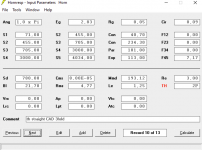
The Exp and Par for L34 and L45 are only for apporaching my model closer to its real properties. I just dont have the tools to build exponential or parabolic throat pieces. I found out that fiddling around with the S1 S2 and S3 diameters help me out with this issue of having bad results bove 90hz. I still prefer to have a tapered section around s1 to at least aproach it. I thought to shorten it in the real model and aproach that by turning the L12 into a parabolic shape.
Attachments
So you guys say it wont be that bad even if it implies assymetric loading due to its narrowing throat?
I thought its maybe worth to add 45° plates around the cornes to reduce diffraction. I dont know how big they are supposed to be, i just designed those by gut feel. They take up around 30 liters, so it does not hurt too much considering the size of the enclosureThe actual shape of the speaker cones and baffle cut outs actually make the real cross sectional areas bigger than the theoretical cross section. So the actual compression may be less than you expect, but in this case I suppose the s2 point is inbetween the 2 drivers and the limitations of Hornresp mean you have to simulate the initial taper finishing at s2 and the displayed compression ratio is also at the restrictive s2 point.
Other designs have used a similar ramp - such as the Orthorn 21 TH. But what does the ramp effect in the design - Is it the top end extension that you will never use? - Are you just reducing the effective volume of the speaker?
The Keystone TH does not use a initial taper for instance.
Btw i already designed the s2 at the middle of those 2 speakers. you cant get lower than 40cm since they are 15sI thought its maybe worth to add 45° plates around the cornes to reduce diffraction. I dont know how big they are supposed to be, i just designed those by gut feel. They take up around 30 liters, so it does not hurt too much considering the size of the enclosure
That's my understanding........So you guys say it wont be that bad even if it implies assymetric loading due to its narrowing throat?
Calculate the plate's effective diameter, then ~34400/pi/dia = its approximate low corner BW, which will normally be well above a sub's XO point's pass band. From this, it's obvious that they need to be huge and why wide BW folded horns have such huge radii.I thought its maybe worth to add 45° plates around the cornes to reduce diffraction. I dont know how big they are supposed to be, i just designed those by gut feel. They take up around 30 liters, so it does not hurt too much considering the size of the enclosure
Also, the plates need to continue the expansion's taper, so will be offset otherwise they will cause reflections back to the driver's throat, which in turn can worst case modulate the driver or at least comb filter with it.
Note too that these 'pockets' act as if stuffed with damping, so best overall to leave well enough alone. 😉

Indeed. I didnt expect so much difference due to big wavelenght. Thanks for sharing your sims.I very much need it sadly... If i dont narrow it to a taper i end up losing usable bandwith... Look at this
If you have doubts, than follow your intuition and go with solution in post #2
Sometimes when you look at it very closely and simulation put into simple terms so that you can keep track of what’s going on and folded in the same way you see something happening that’s unique?The actual shape of the speaker cones and baffle cut outs actually make the real cross sectional areas bigger than the theoretical cross section. So the actual compression may be less than you expect, but in this case I suppose the s2 point is inbetween the 2 drivers and the limitations of Hornresp mean you have to simulate the initial taper finishing at s2 and the displayed compression ratio is also at the restrictive s2 point.
Other designs have used a similar ramp - such as the Orthorn 21 TH. But what does the ramp effect in the design - Is it the top end extension that you will never use? - Are you just reducing the effective volume of the speaker?
The Keystone TH does not use a initial taper for instance.
If this one is zero and S2 is 30 cm if there’s a full at 90 and a fold out 180 and 180 is S3 which is 150 cm after s2 then from 180 to 270 you can increase the CSA proportionally or a 1.66 or 1.25, 2.0 etc as long as you have an opposing parallel section coming from the other side of the con as if it was 360 and then 330 at driver entry 270 at the exit which they both share now as 90 and 270 respectively.
The entire half of the enclosure even though the exit splits that again has got to be the same CSA. Preliminary half or the half on the long side(270) has to be that smaller size CSA. You’re not you cannot table you cannot flare can do anything however you can change the cross-section at that one location(180 in this case ) , it’s also the acoustic center between the two drivers as 150. And if you look further you can reduce that 30 cm section editor and to 7.5 cm and a larger CSA as if it were a throat chamber volume instead of an offset pipe segment ,so to speak.
The only reason this might be particularly unique or points something out specifically because it cost 360 cm/circumference of 360° so it’s easy to keep track of but also frequency as that is the same as time is for seconds(24 hz , 360 cm, 24 hrs 3600x24 seconds and 1440 mintes.
The first of many frequency starting at 864 at 345.6 m/sec(860 at 344 m/sec ) and 1718,2592,3456,4320,5184,6912,7776,8640,9504,10368,11232,12096,12960, 13824, 14688, 15552, 16416, 17280, 18144, 19008,19872, 20736, 21600..
No coincidence that straddles human hearing limitations if you look further into this it’s all directly connected to the same reason why that subwoofer will sound so unique and so uninhibited and clean it wasa perfect oasis sitting in the desert of disasters surrounding it and it’s ‘perfection‘.
Looking at horn response you can see why.
Approaching that design and using other methods and other folding to abbreviate it or contaminate it has incredible costs. Being off by only a few centimeters or folding incorrect in trouble in that 9898 989Being off by only a few centimeters or folding incorrect in trouble in that 90cm sequence of three to one of each side of the driver is recipe for disaster and very much so.
The same exact phenomenon can be seen in off the driver entry at 300 cm length and (0.349206349x) Driver location because it’s the same exact principle except for contributing to it from both sides of a ‘sine wave(360 as a circle) instead of one side .
30 cm is 0.5238 radiahs
60 is 1.0476
300 is 5.238
360 is 6.2857… So we see the relationship between the two when we look at it in radians and wife fills in the third harmonic perfectly The common TL with a driver position precisely at that location and how that only allows you to change the cross-sectional area at the third segment as well otherwise it also gets Squirrley and only these alterations in pipe parts with the same cross-section work.
It makes sense if you look at it into this further as the .5236 is represented as pi divided by six or the perimeter of a rectangle as pie which has 5236 on both ends and 10476 on the long iIt makes sense if you look at it into this further as the .5236 is represented as pi divided by six or the perimeter of a rectangle as pie which has 5236 on both ends and 10476 on the long ends.
At the same time a cube one by one by one and a sphere with a diameter of one will displace 5238at the same time a cube one by one by one and a sphere with a diameter of one will displace 52.38% Volume by comparison and three-dimensional Dido Susie rectangle version in the room of the Egyptian pyramid which the exact same thing with sides is 1309-523Volume by comparison and three-dimensional Dido Susie rectangle version in the room of the Egyptian pyramid which the exact same thing with sides is 1.3095238 What is 1/4 the speed of light or 1/4 300 and radiant heat will see the relationship again what’s going on here and further it I’ll look in a simulation and then finally by listening to the cabinet and wondering why is this same thing represented in the pyramid …. ?? Although it is as a description in a room as a rectangle with a proportionately equal rectangle in it has a fake burial sarcophagus or something ? Supposedly at once on the residence of the ark of the covenant ?? Whatever, nobody has a clue, But in the meantime look at what the heck happened in this enclosure using this exact same architecture description it’s spelled out in that and the pyramid because the details of the pyramid are the same as the numbers of the frequencies that are being canceled out and an even more the math to arrive at those frequencies is in this building and he put it into our on speaker designs and you’re doubling down and all this and then I’ll get down to something very specific. But in the meantime look at what the heck happened in this enclosure using this exact same architecture description it’s spelled out in that and the pyramid because the details of the pyramid are the same as the numbers of the frequencies that are being canceled out and an even more the math to arrive at those frequencies is in this building and he put it into our on speaker designs and you’re doubling down and all this and then I’ll get down to something very specific it’s in the sound but the information is out of the pass band , you can’t see it in the past and it’s perfectly diluted in 10 cm increments. 864(1/10/100)43.22/20/200)28.8(3/30/300-fb) , and everything in between the drivers or from each closed end .
note CSA very strict it appears to use the same Pythagorean theorem that used to describe third planet earth location on the speed of light and it’s orbit around the sun.
How so? In its pistonic BW between Fs - ~VC diameter it acts as a flat piston and if the driver is behind the baffle, then the cutout size = Sd for the purpose of figuring CR, though folks don't seem to factor it in, so CR will be lower than HR predicts in this case.The actual shape of the speaker cones and baffle cut outs actually make the real cross sectional areas bigger than the theoretical cross section.
The secret sauce is always in The driver offser entry (for more than one reason) not only is it a hunter killer for that harmonic spot(3x 1/4 fb) it’s also a fulcrum point if you make it so in a pressure /velocity differential that keeps the cycle going repeatedly just like it does in this video? …Its always a winner if driver entry spacing /synchronicity of the pendulum model/eqiation) unfolding intervals and spacing. It’s always the same it’s always supposed to be the same it always fixes multiple things it makes everything better . And the breakdown of pipe into the odd harmonics is always the winner specially in ODMLT rear chamber pipe, But it makes the parallel version king of them all and fixes everything about it as wellHow so? In its pistonic BW between Fs - ~VC diameter it acts as a flat piston and if the driver is behind the baffle, then the cutout size = Sd for the purpose of figuring CR, though folks don't seem to factor it in, so CR will be lower than HR predicts in this case.
I plan to mount them on the baffle. ill put in m6 inlets into the wood and screw the speakers direclty on the baffle with m6 screws
Yeah i mean how are you getting the physical drivers through the exterior of the box onto the baffle, and then how are you getting your arms in there to bolt the drivers to the baffle.
I assume some fashion of access panel on the rear panel, but i have concerns that your bracing method will make it impossible to install a large enough access panel for the job.
I assume some fashion of access panel on the rear panel, but i have concerns that your bracing method will make it impossible to install a large enough access panel for the job.
I planned to have the whole side screwed with like 60-70 screws and inlets. I literally mean the whole side that lets you look into the box. I wonder if it will still vibrate too much even when using so many screws. The good part of it would be the accesibility to the whole enclosure. If i ever get any rattling because something may or may not loosened up (for what ever reaosn), i can access it.
My guess would be, if it needs any more reinforcement, it would be most likely at the exit of the sub.
My guess would be, if it needs any more reinforcement, it would be most likely at the exit of the sub.
- Home
- Loudspeakers
- Subwoofers
- Insecure about my Subwoofer TH project