I am looking to make device that can measure the differential voltage across a small resistor in the plate circuit of a tube operating with a B+ in excess of 500 volts.
The are devices from TI I have seen that can handle 300 or so volts, but none insanely high I could find. A SOC (system on a chip) ADC will monitor the voltage off the device.
An Idea I have is elevating the ground of the instrumentation amplifier and its VCC power supply. This concerns me because the SOC will need to directly monitor the output of the instrumentation amplifier. If the interface were digital, I could easily optoisolate it.
What do you all think?
Optically isolated V-F...F-V conversion
http://ww1.microchip.com/downloads/en/DeviceDoc/21483d.pdf
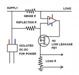
Or use the cct in jpg.
A lot of high side current sense are based on this cct.
You need low offset op-amp.
http://ww1.microchip.com/downloads/en/DeviceDoc/21483d.pdf
Or use the cct in jpg.
A lot of high side current sense are based on this cct.
You need low offset op-amp.
Attachments
Or one of these linear isolators:
http://www.analog.com/static/imported-files/data_sheets/ADuM4190.pdf
http://www.analog.com/static/imported-files/data_sheets/ADuM3190.pdf
http://www.analog.com/static/imported-files/data_sheets/ADuM4190.pdf
http://www.analog.com/static/imported-files/data_sheets/ADuM3190.pdf
Wasn't easy to find, but I am glad it exists. It will save me quite a bit of design time. Thanks. 🙂
Hi,
Just to share this method with you so you can have an idea how to do it in your project.
To read a high voltage with a micro I used the attached circuit. What I do it is used a voltage divider to drop the voltage from 200 volt to 5 volt so the micro A/D can read it. Most of the micro can read a max voltage of 5 volt. I read the voltage from the divider thru an op amp to use it as a buffer just to protect the micro from the high voltage that it is connected. To do the conversion I do the following equation voltage = A/D voltage input * (200/5).
Up to now it is working with no problems.
Attachments
What is the plate load circuit?
A transformer loaded plate circuit without any form of dV/dt or Vpk suppression has the capability of reaching very high transient voltage levels due to leakage inductance and fast dI/dt from a number of sources. In its simplest sense, Vpk will be twice B+.
A transformer loaded plate circuit without any form of dV/dt or Vpk suppression has the capability of reaching very high transient voltage levels due to leakage inductance and fast dI/dt from a number of sources. In its simplest sense, Vpk will be twice B+.
I am using the Linear Technology LTC6101 device. By itself it doesn't handle much. Download their app notes that tell you how to make them work up to kilovolt regions. I have simulated a bench power supply design that will put out 0 to 750 volts and 0 to 2 amps using their simulator (LT spice).
I have breadboarded and tested the current sensor and pass device circuitry and verified the ability to put a screwdriver across the output terminals at full output without vaporizing silicon! Note, I have only tested to 650 volts into the circuit and 600 out, because that's all my current power supply can do.
See page "high side 4" in this app note.
http://cds.linear.com/docs/en/application-note/an105.pdf
I believe that you could even use the TI part (INA168) in that circuit, but I have not tried it.
COOL
But I don't know if I would want 500V 0.030" from GND or -Vcc potential on my PCB.
IMO
🙂
Hi,
I used the hall effect current sensor ACS712. They come in 5,12,20,30,50,100 amps. I am using it to read the speaker output current and shutdown if the current reached the setting point.
link:Allegro MicroSystems - ACS712: Fully Integrated, Hall-Effect-Based Linear Current Sensor IC with 2.1 kVRMS Voltage Isolation and a Low-Resistance Current Conductor
If you are just wanting to measure plate current, all you have to do is put a current sense resistor in the GND return line of the power supply. If pentode screen current is an issue, then use a separate power supply for the screen.
If you are just wanting to measure plate current, all you have to do is put a current sense resistor in the GND return line of the power supply. If pentode screen current is an issue, then use a separate power supply for the screen.
The power supply GND may also include screen and other plate currents...not just final plate current.
Hi,
I used the hall effect current sensor ACS712. They come in 5,12,20,30,50,100 amps. I am using it to read the speaker output current and shutdown if the current reached the setting point.
link:Allegro MicroSystems - ACS712: Fully Integrated, Hall-Effect-Based Linear Current Sensor IC with 2.1 kVRMS Voltage Isolation and a Low-Resistance Current Conductor
An excellent use for these as we have had to implement gain/offset trim to use these for absolute current sense.
I did not know they came in 50A and 100A versions (I've only seen 5,20,30)...What package do they use for the 100A?
I don't know if I would want even 50A on two pins of an soic package.
🙂
Last edited:
"The power supply GND may also include screen and other plate currents...not just final plate current. "
You just use a separate power supply for the screen V, and optionally for the front end too.
Since the front end tubes are typically running class A, they are drawing near constant current, so you can just subtract a constant from the final GND current meter reading.
(Just measure the GND current to the front end once. The subtraction could then be done automatically from the meter readout by a resistor trim from V- or an offset adjust, if you don't want to do the math everytime.)
Hall effect devices will likely have some thermal drift unless well compensated.
- Status
- Not open for further replies.
- Home
- Amplifiers
- Tubes / Valves
- Insanely High Common Mode Voltage Shunt Measurement