Hello all.
I'm planning a new headphone amplifier that will use triodes for the input stage. It's based on Gilmore's dynamic class-A amplifier even though it's going to be class AB. The idea is to build an amp with a differential input stage, paralleled output transistors, and a bipolar supply. Projected output capability will be 500 mW into 8 ohms (yes, it is a flea-powered amp with a headphone output).
The purpose for this design is for future projects. I want to learn the principles behind amplifier design in topologies such as this. If I can build a 500 mW amp then I can use the same schematic with stronger transistors and a stouter power supply in order to get something on the order of 30 watts. Then I can do it again with a larger transformer and build a 150 watt amp.
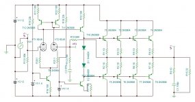
This is the schematic. Although the transistors are all labeled 3904/3906, I plan to use 2SC1815s and 2SA1015s for all of the BJTs. I'm going to prototype the amplifier with MPF102s in the input stage, using a 500-ohm trimmer in the source circuit for DC offset nulling. Once I can find a stable operating point, I'm going to plug-and-play output transistors until I can get a set of 8 with reasonably matched levels of current. After I get a stable, working amplifier I might build a prototype, which will likely turn out to be a gift amp or something I sell. Then, I'll build it again on the breadboard and use a tube as the input differential. I considered using 6922 but I'm thinking of using 6N2P because I have three dozen of them. 6N2P is a Russian 12AX7-clone with a 6DJ8 base and there was never an American equivalent.

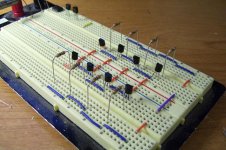
This is the set of output transistors on the breadboard. If I had more 1/4w, 10 ohm resistors, I'd measure each one and match the whole set within 1%. Those output transistors will be matched as closely as I can get them. I've been busy so I've only been able to set up the output stage and the two bias diodes.
I already posted this project on diyaudioprojects.com but no one's given me any feedback. I figured I'd put it out here and see what people had to say.
Ed

I'm planning a new headphone amplifier that will use triodes for the input stage. It's based on Gilmore's dynamic class-A amplifier even though it's going to be class AB. The idea is to build an amp with a differential input stage, paralleled output transistors, and a bipolar supply. Projected output capability will be 500 mW into 8 ohms (yes, it is a flea-powered amp with a headphone output).
The purpose for this design is for future projects. I want to learn the principles behind amplifier design in topologies such as this. If I can build a 500 mW amp then I can use the same schematic with stronger transistors and a stouter power supply in order to get something on the order of 30 watts. Then I can do it again with a larger transformer and build a 150 watt amp.
This is the schematic. Although the transistors are all labeled 3904/3906, I plan to use 2SC1815s and 2SA1015s for all of the BJTs. I'm going to prototype the amplifier with MPF102s in the input stage, using a 500-ohm trimmer in the source circuit for DC offset nulling. Once I can find a stable operating point, I'm going to plug-and-play output transistors until I can get a set of 8 with reasonably matched levels of current. After I get a stable, working amplifier I might build a prototype, which will likely turn out to be a gift amp or something I sell. Then, I'll build it again on the breadboard and use a tube as the input differential. I considered using 6922 but I'm thinking of using 6N2P because I have three dozen of them. 6N2P is a Russian 12AX7-clone with a 6DJ8 base and there was never an American equivalent.

This is the set of output transistors on the breadboard. If I had more 1/4w, 10 ohm resistors, I'd measure each one and match the whole set within 1%. Those output transistors will be matched as closely as I can get them. I've been busy so I've only been able to set up the output stage and the two bias diodes.
I already posted this project on diyaudioprojects.com but no one's given me any feedback. I figured I'd put it out here and see what people had to say.
Ed

The great advantage of triodes is plate voltage linearity.
I don't see that here. You hold both plates 1 diode drop
from the top rail. Triodes are not incredibly linear in Gm
without plate voltage/Mu feedback.
If you won't let Mu linearize, what's supposed to be the
advantage (oh-say, compared to JFETs)?
I don't see that here. You hold both plates 1 diode drop
from the top rail. Triodes are not incredibly linear in Gm
without plate voltage/Mu feedback.
If you won't let Mu linearize, what's supposed to be the
advantage (oh-say, compared to JFETs)?
Oops...I seem to have placed the wrong schematic here. One of those triode plates is supposed to be stuck to the top rail and the other is supposed to connect via a resistor to it. The one with the resistor feeds the VAS and both have a 500-ohm trimmer in their cathode circuit, the wiper connected to the CCS for balance control. I will see if I can find the right schematic and place it here.
I'm not exactly sure what you mean...do you think you can explain it? Any helpful advice is welcome.
Ed
I'm not exactly sure what you mean...do you think you can explain it? Any helpful advice is welcome.
Ed
- Status
- Not open for further replies.