The circuit you show is not a inrush-currant limiter .
Please look at the forum e.g. solid state to find a adequate circuit
You will find tons of that . For a 800VA -X-former a limiter is a must!
I would prefer a circuit with a resistor of ca. 50 Ohms with the delayed
relais.
ingo
Please look at the forum e.g. solid state to find a adequate circuit
You will find tons of that . For a 800VA -X-former a limiter is a must!
I would prefer a circuit with a resistor of ca. 50 Ohms with the delayed
relais.
ingo

connect the relay coil to the "C" of an "R-C" cct across one of the psu rails, this will give you the delayed turn on.
Thanks.
Ok, I builded this circuit who offer with 1000uF a time delay of 4 sec at coupling and 7 sec around to decouple. Unfortunately the case of relay I used is sealed and black so no spark can be seen. Please let me know how I can evaluate the MINIMUM time delay necessary to get safe operation to fit the right capacitor value in place please ? How much percent the capacitors should be charged to be sure I may close the circuit over 33 ohm limiter without risk to get sparks at the relay contacts please ? I.ll be comfortable under 1 sec delay but not sure it work safe...Thank you..

Ok, I builded this circuit who offer with 1000uF a time delay of 4 sec at coupling and 7 sec around to decouple. Unfortunately the case of relay I used is sealed and black so no spark can be seen. Please let me know how I can evaluate the MINIMUM time delay necessary to get safe operation to fit the right capacitor value in place please ? How much percent the capacitors should be charged to be sure I may close the circuit over 33 ohm limiter without risk to get sparks at the relay contacts please ? I.ll be comfortable under 1 sec delay but not sure it work safe...Thank you..
Last edited:
Here is an example of solution >
https://www.ebay.com.au/itm/3256609...Dp3twOFQwrhjaT3dVoR+ehhg==|tkp:Bk9SR8zYgNvZZQ
For my 600VA transformer I have bought the '10ohm / 5amp' version. I'm running @ 240Vac.
[ these are wired to the input of the transformer ]
https://www.ebay.com.au/itm/3256609...Dp3twOFQwrhjaT3dVoR+ehhg==|tkp:Bk9SR8zYgNvZZQ
For my 600VA transformer I have bought the '10ohm / 5amp' version. I'm running @ 240Vac.
[ these are wired to the input of the transformer ]
Maybe something like this?
https://www.diyaudio.com/community/...-soft-start-circuit.248900/page-2#post3782219
#23 and #31
https://www.diyaudio.com/community/...-soft-start-circuit.248900/page-2#post3782219
#23 and #31
That was exactly what initial did. Couple of miliseconds was not enough to limit the current at a value the relay contacts don't arcing. It simply not work. The guy who posted did not see the arcing inside.
Last edited:
Strange, I have used similar circuit as a soft-start for a 3kVA transformer for years, never any problem. Be sure to use a relay that doesn't close on to low voltage, and a power resistor with small resistance. You should provide some cooling to the resistor if You experience series' of power outage, it gets warm.That was exactly what initial did. Couple of miliseconds was not enough to limit the current at a value the relay contacts don't arcing. It simply not work. The guy who posted did not see the arcing inside.
Quick and dirty : (Supply voltage) / (Current limit for circuit breaker) = (minimum resistor + resistance in primary winding)
Take every precaution, especially on resistor lead thickness, wattage and so on
https://www.diyaudio.com/community/attachments/sspb2-jpg.394370/
I used a 230Vac relay. It close at 130V and the resistor used was 33ohmStrange, I have used similar circuit as a soft-start for a 3kVA transformer for years, never any problem. Be sure to use a relay that doesn't close on to low voltage, and a power resistor with small resistance. You should provide some cooling to the resistor if You experience series' of power outage, it gets warm.
Quick and dirty : (Supply voltage) / (Current limit for circuit breaker) = (minimum resistor + resistance in primary winding)
Take every precaution, especially on resistor lead thickness, wattage and so on
https://www.diyaudio.com/community/attachments/sspb2-jpg.394370/
I would change to a DC relay.
Solder a diode across the relay terminals.
That will cure the spark.
More information at:
https://components.omron.com/us-en/solutions/relays/power-relays-support
Regards
Mike
AmpsLab

Solder a diode across the relay terminals.
That will cure the spark.
More information at:
https://components.omron.com/us-en/solutions/relays/power-relays-support
Regards
Mike
AmpsLab
simplest mod you can do to the circuit in the first post ( tester by me always worked fine)
connect the coil of the relay at the secondary of the transformer, put a diode in series to transform AC in DC, put a 470uF cap in parallelo to the coil. chose a relay with a coil voltage appropriate to the secondary voltage or insert a resistor to limit the coil current to a safe value
connect the coil of the relay at the secondary of the transformer, put a diode in series to transform AC in DC, put a 470uF cap in parallelo to the coil. chose a relay with a coil voltage appropriate to the secondary voltage or insert a resistor to limit the coil current to a safe value
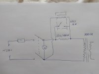
Hello. I tried to do a limiter current circuit at start up for my 800va transformer. I get severe spark at contacts and asking for a solution to cure it please. Thank You. Circuit below:
BTW, that's not a Current Limiter. The resistor limits the current but there's no delay for the relay.
This is what a Current Limiter circuit looks like.
There are other ways of doing this but the main idea is to tame the inrush current with a resistor then short it out with a relay.
Generally, I delay the relay for about 1/2 sec.
Enough to arrest the current surge.
Mike
AmpsLab
Catalin gramada, perhaps firstly confirm what is loading the secondary side of your transformer ? It may be that your limiter aims to not only suppress the first one or two cycles of mains for primary in-rush, but also in-rush into secondary side circuitry.
Thanks. I already changed to a dc relay supplied by 1000uF cap for 3-4 sec delay as it was suggested above.

Last edited:

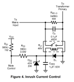
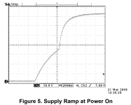
That's how Texas Instruments does it in their application note AN-1849.connect the relay coil to the "C" of an "R-C" cct across one of the psu rails, this will give you the delayed turn on.
Choose the relay coil voltage, the zener diode voltage, and the values of RZ1 and RZ2 from an analysis of the asymptotic steady state value of the PSU DC voltage. In the TI example, the steady state PSU DC voltage was 72V. They chose a 48V relay coil, a 43V zener diode, and Rz1+Rz2 to provide a total of 30mA through the zener diode plus the relay coil. The scope photo shows that their inrush limiter is active for about 500 milliseconds, and then the relay bypasses (shorts out) the limiter. Of course you can modify the time delay by adjusting the value of capacitor Csr2.
"Vcc" is the DC +72V output of the power supply, after the transformer, rectifiers, and bulk filter capacitors.
In this arrangement, the mains on/off switch carries the full supply current and must withstand the full supply voltage. It's got to be a beefy, macho unit. Not a cute little touch button on the front panel. Or else you can implement a second relay or an SSR or a triac, for the on/off switch.
_
Attachments
Last edited:
- Home
- Amplifiers
- Power Supplies
- Inrush limiter relay issue