Yes plenty of threads here about soft starts but mostly for limiting inrush current to
big transformers.
I get annoyed with arcs from plugging in SMPS . (all kinds of chargers and laptop
power brick)
Now I want to use something like :
https://www.mouser.com/ProductDetai...=/ha2pyFaduhrXXPY0wcvNaPZ/Bs7PbwQ8t4UKq8ikqk=
Datasheet says typical 45 A inrush current , what the H ?😡
How to limit this with minimal power loss , so no relays , triacs ( around 1,5 V
loss) . Affordable HVmosfets seem the only way.
Instead of the usual inrush current resistor , rather a cap.
I've used mosfets like this before to remotely switch on an amp's transformer and
limit inrush current but using resistors.
Will something like this work with SMPS ?
The SMPS will not be delivering current to its load when switched on , more like
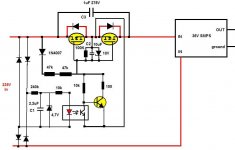
standby , so 1uF should be more enough and to keep the size of C3 down except maybe for small power cuts.
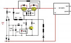
At the start C2 slows the gate voltage of the mosfets.
The opto and transistor are there to quickly discharge C2 . I have frequent power
downs of seconds and if the mosfets still conduct when power comes back , they
could get the 45 A inrush current which would kill them.
C1 is for smoothing the 100 hz ripple for the LED.
Mosfets shouldn't be expensive , like : https://www.mouser.com/ProductDetai...IPN70R2K0P7SATMA1?qs=W0yvOO0ixfEdA016odOi9g==
For sure if the mosfets have to take a 45 A hit , a little more expensive :
https://www.mouser.com/ProductDetai...0R210PFD7SAUMA1?qs=BJlw7L4Cy7%2BeTPhGuha9Jw==
Yes Tomchr does something simular : The Ultimate Guide to Soft Start Design – Neurochrome , near the end , but I can't find opto-mosfets for high voltages and high currents.
big transformers.
I get annoyed with arcs from plugging in SMPS . (all kinds of chargers and laptop
power brick)
Now I want to use something like :
https://www.mouser.com/ProductDetai...=/ha2pyFaduhrXXPY0wcvNaPZ/Bs7PbwQ8t4UKq8ikqk=
Datasheet says typical 45 A inrush current , what the H ?😡
How to limit this with minimal power loss , so no relays , triacs ( around 1,5 V
loss) . Affordable HVmosfets seem the only way.
Instead of the usual inrush current resistor , rather a cap.
I've used mosfets like this before to remotely switch on an amp's transformer and
limit inrush current but using resistors.
Will something like this work with SMPS ?
The SMPS will not be delivering current to its load when switched on , more like
standby , so 1uF should be more enough and to keep the size of C3 down except maybe for small power cuts.
At the start C2 slows the gate voltage of the mosfets.
The opto and transistor are there to quickly discharge C2 . I have frequent power
downs of seconds and if the mosfets still conduct when power comes back , they
could get the 45 A inrush current which would kill them.
C1 is for smoothing the 100 hz ripple for the LED.
Mosfets shouldn't be expensive , like : https://www.mouser.com/ProductDetai...IPN70R2K0P7SATMA1?qs=W0yvOO0ixfEdA016odOi9g==
For sure if the mosfets have to take a 45 A hit , a little more expensive :
https://www.mouser.com/ProductDetai...0R210PFD7SAUMA1?qs=BJlw7L4Cy7%2BeTPhGuha9Jw==
Yes Tomchr does something simular : The Ultimate Guide to Soft Start Design – Neurochrome , near the end , but I can't find opto-mosfets for high voltages and high currents.
Attachments
See the circuits used for soft starting star delta connected 3 phase motors.
If motors are to be used with generators for example, the generator has to be able to provide the high current drawn in star mode, which is usually a few seconds, and the cables need to be heavy.
To get around this, soft starting circuits, which build up speed slowly were developed. They control the current drawn, and also provide control functions not available in normal thermal relay based starters.
Might be useful to you.
Rick, that current spike is not "inrush" in the transformer sense. It is simply charging the capacitor sitting across the mains at the instance of connection and lasts for a very short 440uS. Its function is to prevent the SMPS high frequency current noise feeding back into the mains network.
So all you need is a small high current inductor of a few uH. Five or ten turns of insulated wire on a short 5mm bolt held together and insulated with heatshrink tubing. Connected in series with one of the mains wires.
This will limit (slow down) the rate of rise of the capacitor charging current and thus limit the peak current.
Although, if the manufacturer does not care about it, why should you?
^ Are you sure ? I think that it is the peak current rushing/loading the capacitor after the rectifier to the max of about 385 V (on a 230-240Vac mains).
Caps to surpress/prevent the SMPS high frequency current noise , are much smaller and don't have a massive current draw that can cause an arc.
Yes it seems manufacturers don't care . If it was easily and cost-effective solved , why wouldn't they implement it.
If I plug in my laptop power brick at the wrong time , the lights flash . Even smaller ones like 12 V SMPS of an external harddrive arc . Bad engineering .
A 45 A typical inrush current like on the Mean Well datasheet in the link is riduculous , even for 0,44ms .
Motors , 3 phase or not , are inductive.See the circuits used for soft starting star delta connected 3 phase motors.
Here for a SMPS it is capacitive.
It is a gradual rise to full voltage by IGBT units in soft starters.
Earlier it was thyristors and triacs
Earlier it was thyristors and triacs
I use 5 ohm (cold) NTC inrush current limiters with my 220V mains and yes, that boils down to 44A peak. (nominal)
Which is fine.
With this SMPS I´m replacing a 450VA EI transformer supply in my 300W Bass Guitar amps and it *also* dims the lights for a fraction of a second at turn on.
Caps are caps and need charging.
You might design and use a slooooowwww turn on circuit, why not?
Typically not deemed indispensable but hey, to each his own.
If we are talking about a smps that is nothing more than a booster then you’re going to not control inrush - there’s no switch or no blocking capacitor (ie cuk).
A more advanced smps with pfc with an upper get that is in series with the live would control inrush.
A proper tube amp smps needs to be both isolated and have a topology for inrush control - even active rectification. However as long as people buy basic smps that do the job, people won’t develop anything else..
I see lots of issues: the 1µF ballast will not have a low enough impedance to charge properly the filter cap of the supply, and the suppy itself will be starved.
When the MOS conduct, they will be subjected to a significant step, and in addition they will have to discharge the 1µF.
Anyway, the circuit cannot work properly: to generate a gate voltage, the MOS cannot conduct fully, they will have 10V or so across them.
The opto should be eliminated, and the auxiliary supply should generate the gate voltage from the hot and cold wires, not just from the hot one
Thanks Elvee , but I don't agree on everything.
Like I said the SMPS will be on standy at the start which draws very little current so the input cap will slowly charge enough.
I didn't think of the discharging of the 1uF , but with a slow rising gate voltage , the mosfet should be able to handle the current. But when the input cap of the SMPS nearly charged , will there be a big voltage and current on the 1 uF ?
I could exchange the cap for a resistor.
This is based on a power on circuit I made 20 years ago , which works perfectly , but is slightly different , and you are right , when the mosfet here conducts , there is no gate voltage.
No the opto is , in my case, needed for fast power down .
Would the aux supply generated from the 2 wires make it work ?
Attachments
A SMPS behaves like a negative resistance: it draws more current when the input voltage decreases, and if the series impedance is too large, there will be a cumulative effect where the supply draws more and more current to combat what it sees as a brownout, until the voltage collapses completely.
This will cause a hiccup effect.
Before you embark on this path, you should check that the supply remains stable with the 3.2K series impedance of the capacitor.
To manage the short-circuiting current of the capacitor, you can add a series resistor, of 100 ohm for example: it will have no effect on the 3.2K, but will limit the surge to ~3A.
Your auxiliary supply will probably work, and I am pretty sure that it would be possible to include the fast turnoff circuit in it, and to dispense with the opto.
I probably have such a circuit in my archives, but I am not sure I'll be able to locate it.
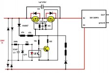
If you keep your opto, it would be a good idea to tidy up the circuit: placing the rectifier bridge directly across the mains is not required, and is risky as a transient could cause a catastrophic failure. By placing your 240K on the AC side, you will protect the diodes, and you will be able to use ordinary 1N4148's.
You could also use a capacitive dropper instead of the resistor, but it is probably not worth the small dissipation gain
This will cause a hiccup effect.
Before you embark on this path, you should check that the supply remains stable with the 3.2K series impedance of the capacitor.
To manage the short-circuiting current of the capacitor, you can add a series resistor, of 100 ohm for example: it will have no effect on the 3.2K, but will limit the surge to ~3A.
Your auxiliary supply will probably work, and I am pretty sure that it would be possible to include the fast turnoff circuit in it, and to dispense with the opto.
I probably have such a circuit in my archives, but I am not sure I'll be able to locate it.
If you keep your opto, it would be a good idea to tidy up the circuit: placing the rectifier bridge directly across the mains is not required, and is risky as a transient could cause a catastrophic failure. By placing your 240K on the AC side, you will protect the diodes, and you will be able to use ordinary 1N4148's.
You could also use a capacitive dropper instead of the resistor, but it is probably not worth the small dissipation gain
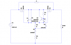
I didn't find the exact circuit I was looking for, but I found somtehing closely related: it is a power delay timer:
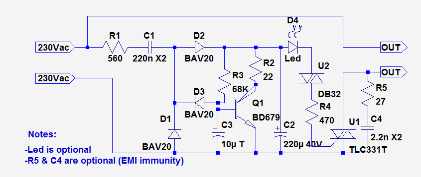
The output is a triac, but the core can be reused: you just need to adapt the values, and place a 10V zener in // with C2.
The darlington can be a BC516, or alternatively a small mosfet with an adapted value of C3.
As the circuit had to supply the gate of a triac, the current level is relatively high, but for mosfets you can make the impedance level X10.
The capacitive dropper C1 can be replaced with a plain resistor
Attachments
Your cicuit in post #12 doesn 't seem to have a quick power down or is it done by going under the holding current of the triac ? Mosfets don't have a minimum holding current.
I don't get what the triac is bypassing .
I don't get what the triac is bypassing .
Opt for anything convenient, R or R-C, but make sure that the supply is stable with itThanks Elvee.
Maybe just replace the 1uF with a resistor , 1k 10 W or so.
It is not a matter of cost, but reliability: having an uninterrupted chain of semiconductor devices between the terminals of an ~unlimited supply is always a risk, protection or not.For simplicity I didn't add VDR's to address transients. 1N4148 or 600 V diodes doesn't matter much. I have ES1J or RFU02V , they 're cheap.
With a small topological mod, the issue can be eliminated completely, it is thus the way to go.
In this form the circuit I proposed does not support the fast power-down. Mods are probably possible, and I probably have a suitable circuit, but I'll need to dig a bit deeper
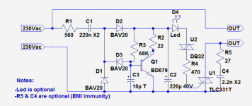
Correction:
In fact, the circuit supports fast turnoff, thanks to D3: when the AC input disappears, D3 stops discharging C3, making the transistor to conduct after a small delay.
The parameters can be adjusted to taste with the components values.
In fact, the circuit supports fast turnoff, thanks to D3: when the AC input disappears, D3 stops discharging C3, making the transistor to conduct after a small delay.
The parameters can be adjusted to taste with the components values.
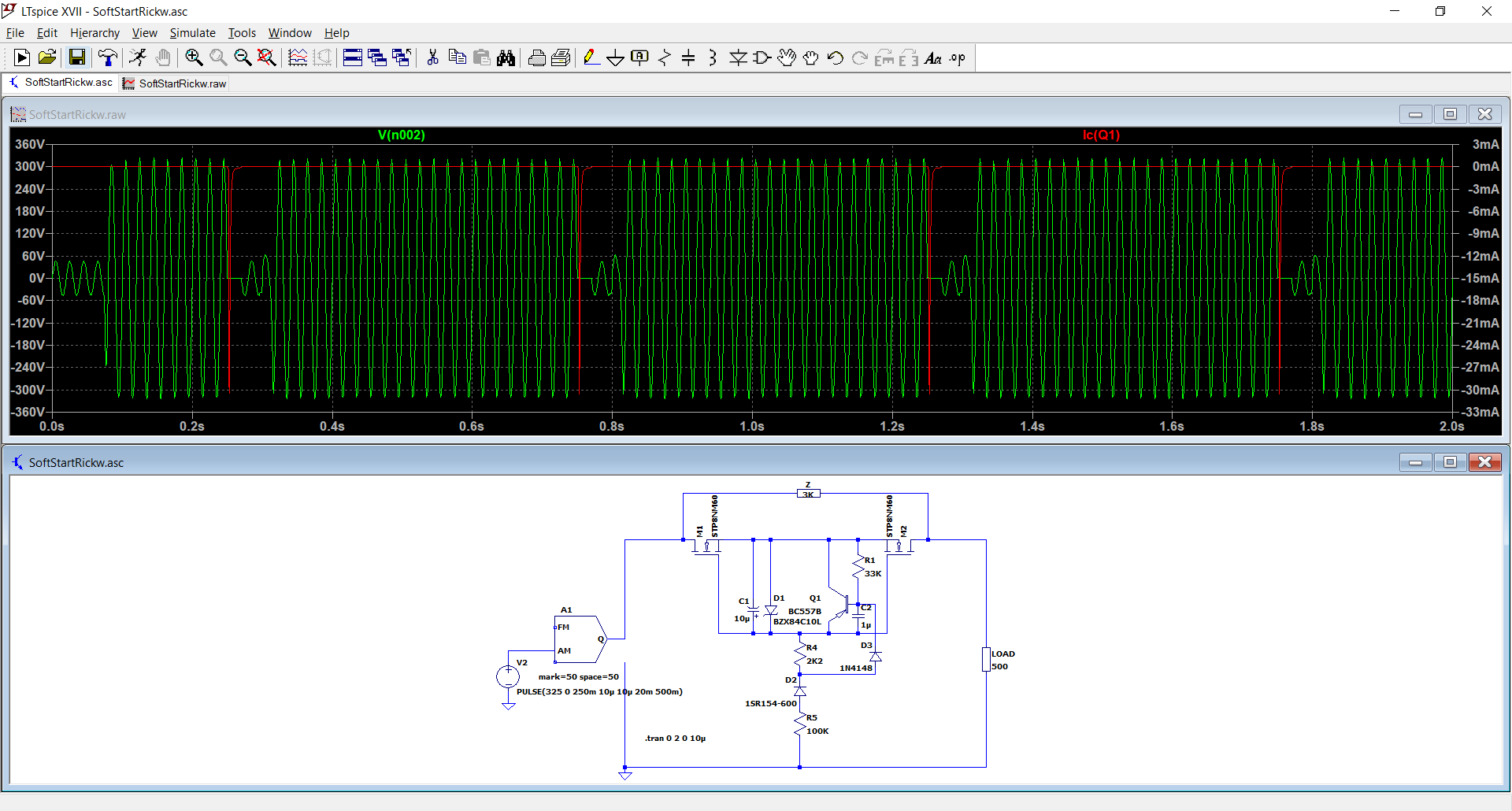
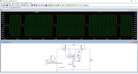
Here is the proposition with realistic values plugged-in.
The test waveform is a 230VAC tone burst, with 20ms pauses between the 500ms bursts.
The green waveform is the output across the load, and the red one the discharge current of C1 through the collector of Q1:
Some more details with these waveforms: red is the same, green is the B-E voltage of Q1, and blue the voltage across C1:
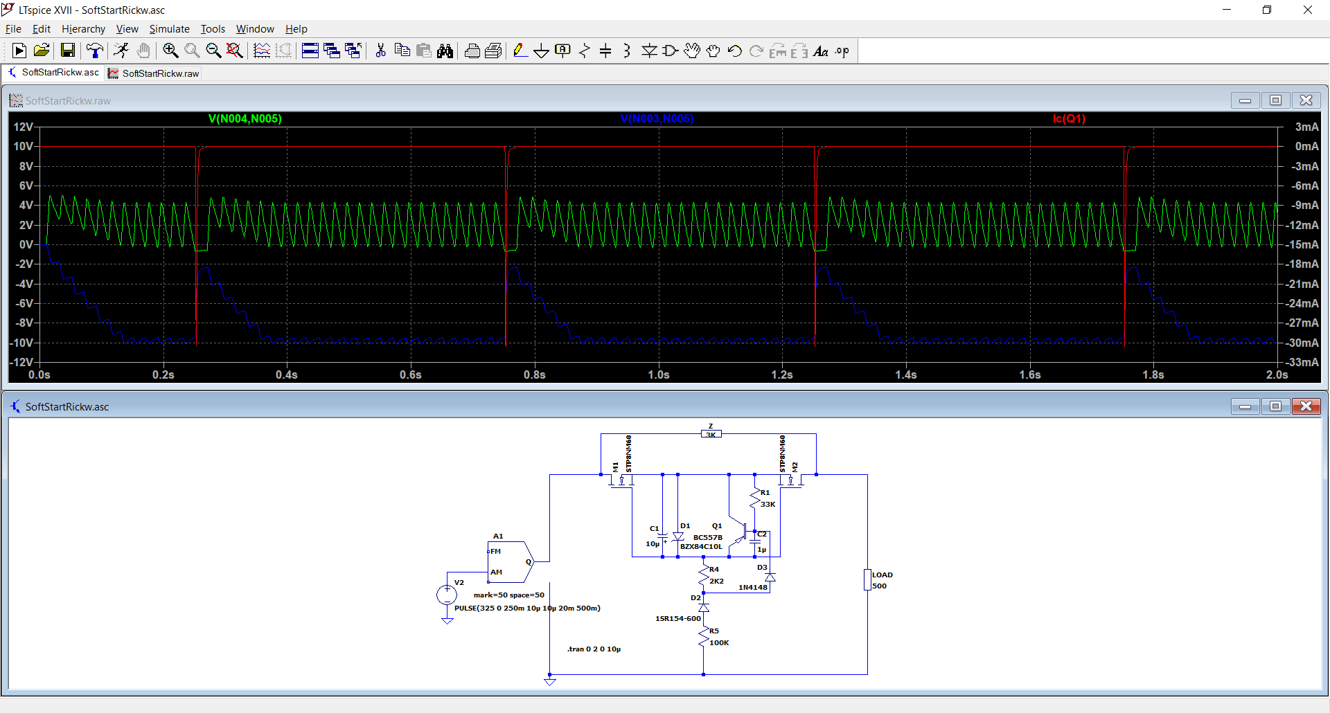
During normal operation, the B-E voltage stays just below the conduction, but as soon as a cycle is missing, it makes the transistor conduct and discharge C1.
The sim is reasonably accurate for this kind of circuit, and it should work as expected, but be aware that if Z isn't low enough to precharge the supply caps sufficiently before the MOSfets conduct, they will be fried; this is your choice & responsability.
The components can be scaled to save power: for example, double all the resistors values and halve all the caps
The test waveform is a 230VAC tone burst, with 20ms pauses between the 500ms bursts.
The green waveform is the output across the load, and the red one the discharge current of C1 through the collector of Q1:
Some more details with these waveforms: red is the same, green is the B-E voltage of Q1, and blue the voltage across C1:
During normal operation, the B-E voltage stays just below the conduction, but as soon as a cycle is missing, it makes the transistor conduct and discharge C1.
The sim is reasonably accurate for this kind of circuit, and it should work as expected, but be aware that if Z isn't low enough to precharge the supply caps sufficiently before the MOSfets conduct, they will be fried; this is your choice & responsability.
The components can be scaled to save power: for example, double all the resistors values and halve all the caps
Attachments

Wow Elvee , you really went to bat for me.
I like what you've designed here and it is even simpler than mine. I didn't really get your first one with the triac and BAV20 (200V) and BD679 (only 80V) and R1 only 560 ohm. I'm not that familiar with triacs and diacs.
Like I said before , it is a matter of cost , because why wouldn't manufacturers implement something like this for all chargers/SMPS ? I can't be the only one (very) bothered with these arcs or dimming lights when plugging in.
Yes when I have the SMPS and power fets , I need to do some measuring , maybe a little more than 60 V at the start and for longer so it goes smoother from 60 to 300 V, going lower than the 3k for Z and higher current mosfets so they don't get fried .
With a power cut , the load may be connected and the input cap may not charge sufficiently.
Thanks Elvee !
I'm not sure this inrush goes from X2 cap only. I think the main portion of it is a main low-freq. filter capacitor charging current.Rick, that current spike is not "inrush" in the transformer sense. It is simply charging the capacitor sitting across the mains at the instance of connection and lasts for a very short 440uS. Its function is to prevent the SMPS high frequency current noise feeding back into the mains network.
Yes, the sparks we see are from X2 caps, but the larger portion of inrush is a charging of electrolytes.
- Home
- Amplifiers
- Power Supplies
- Inrush current limiter for SMPS