Yes, there is difference.
Capacitive load at DC? It equals to 0A. No such thing. The load is an amplifier. Peak current draw must be calculated and served. Capacitor helps doing this.
There is current flow in the reservoir caps during the rise time of the PSU output voltage following a cold start. If the caps are to big then the PSU can see that as a fault condition.
Those are faulty by design.
No. They are just being used outside their design envelope.
It seems we all have our own ideas as to what to do in a case like this. My recommend stays the same in trying to reduce the total value of C.
For those who enjoy such pastimes, it is a pleasant and rewarding problem in circuit design to create a SmearJob circuit which fits between an SMPS and a large bank of electrolytic capacitors.
How about this simple circuit (for a positive rail)?
It doesn't 'sense' any voltage, but would it limit the current for
a little while?
http://www.smsmatrix.com/tmp/amp/inrush_limiter.jpg
Put it into a simulator and find out how well it works! Personally I suspect that the 10nF capacitor directly shorted to the 10uF capacitor, guarantees that the small capacitor has ~ no effect upon the PMOS gate waveform, and nothing would change if you completely removed the 10nF capacitor. However,
The purpose of computer simulation is to correct faulty human intuition.
_OP, are the amp modules stock, or did you customise/design the level of input supply local bypass capacitance?
There is no information presented on the smps - it could be extremely basic or an off the shelf commercial unit or ??? One can't generalise on what a smps response would be - and can only hope it has some form of over-current regulation scheme - which could be anything from constant V/constant I to some form of foldback (which appears to be the more likely).
Did you try and power up just one amp channel from cold (assuming each channel has its own capacitance)?
Why are you using one smps for both channels?
OP, are the amp modules stock, or did you customise/design the level of input supply local bypass capacitance?
There is no information presented on the smps - it could be extremely basic or an off the shelf commercial unit or ??? One can't generalise on what a smps response would be - and can only hope it has some form of over-current regulation scheme - which could be anything from constant V/constant I to some form of foldback (which appears to be the more likely).
Did you try and power up just one amp channel from cold (assuming each channel has its own capacitance)?
Why are you using one smps for both channels?
Amp modules are built by me (but not designed)
See this link: Project 54 | BuildAudioAmps
1 amp channel (2x2700uF) works fine (cold start).
According to smps specs, it should work fine with up to 6800uF
per rail.
It has some kind of over-current regulation circuitry, and I know
which resistor can be changed to modify the max current allowed,
but I don't want to mess with it (yet) for 2 reasons:
1) it's SMD. I've never done SMD, and don't plan to, unless I have to
2) it's pain to disassemble whole amp and take it out.
the amp is finished, cased and being used daily.
I'm using 1 smps for both channels because:
1) theoretically it should provide enough power for both channels
2) I don't really need all this power at home, 700W ought to be enough
for anybody
3) there was no space in the chassis for two of them.
I actually purchased 2 smps-es and was planning to use one per
channel, but due to space constraints, decided to use only one.
They were slightly bigger than I planned for.
http://www.smsmatrix.com/tmp/amp/amp_p54_finished1.jpg
Last edited:
How did you conclude that from the specs?According to smps specs, it should work fine with up to 6800uF per rail.
How did you conclude that from the specs?
I was told by smps' designer/seller.
Last edited:
Its all about capacitor charge times vs frequency.
The time between charging impulses at 50Hz (100Hz rectified) is 10mS.
At 100Khz as in a SMPS it is 5uS.
This means you need a massively smaller capacitor to do the same job.
The SPMS allowing longer times for larger capacitors at amp is a compromise.
The problem comes when a real short circuit occurs and the SPMS doesn't switch off in time to stop failure of its mosfets.
On the other hand you dont want it tripping at slightest overload.
Last edited:
Who said the smps has FETs? The OP hasn't identified the make, model or specs - and appears to have believed what the salesperson said !
Who said the smps has FETs? The OP hasn't identified the make, model or specs - and appears to have believed what the salesperson said !
It's a DIY smps. Has FETs.
Bought it from the guy that runs Page Title
With email support.
Picture: http://www.smsmatrix.com/tmp/amp/smps_1.jpg
Who said the smps has FETs? The OP hasn't identified the make, model or specs - and appears to have believed what the salesperson said !
Apparently you are not one of them 'trusting' people 🙂
Usually when you buy something, you HAVE TO believe
what seller says, unless you have better options, or at least
you do believe in SOME things he says.
When you buy a car, do you really believe it does 30mpg ?
Hell no, but you still buy it... You not going to build it yourself....
Who said the smps has FETs? The OP hasn't identified the make, model or specs - and appears to have believed what the salesperson said !
No need.
mosfets are pretty standard in SMPS.
I have designed a couple of SMPS myself.
One was flyback and the other LLC.
I wrote the software for a PIC to control the SMPS.
The PIC did the LLC frequencies too.
Do you have any tech details, or can link to anything - there didn't seem to be any product details on that website (only a forum and some possible blog/posts), or about/contact details of who/company is presenting the website. Do you really only have a photo?
The photo appears to show a pcb that has been designed to meet some standards, given the routed sections to improve creepage.
The photo appears to show a pcb that has been designed to meet some standards, given the routed sections to improve creepage.
Last edited:
Do you have any tech details, or can link to anything - there didn't seem to be any product details on that website (only a forum and some possible blog/posts), or about/contact details of who/company is presenting the website. Do you really only have a photo?
The photo appears to show a pcb that has been designed to meet some standards, given the routed sections to improve creepage.
This is as close as it gets:
diysmps
Sami (MicroSim) has been making and selling this design since 2012, so I guess some things may have changed. He is constantly improving it.
He's discussing some aspects of his design on the forum.
and of course it's not 1 kW, it's 700W.
It's nicely made, not expensive, and my amp works really well with it
as far as sound quality and distortions go.
Last edited:
Thanks for link - that helps appreciate the situation you are in.
Typically you can only sell a power supply to the public and connect to the mains AC when it has passed standards or regulations applicable to your country - so I guess you take that risk on yourself.
Unless you have somehow got a problem with your amp modules, or they initially pump out a lot of power (eg. you could disconnect speaker load and see if that has an impact, or observe output and input voltages to see if oscillating) and hence add extra loading when the capacitance is charging up, then I suggest you send the smps back for warranty, or seek some form of assistance from supplier, as the claimed performance is not met.
The smps uses IGBTs, not FETs, and is proprietary, and I would not recommend making any alteration to part values as over-current protection changes may affect device stresses beyond what was designed for.
It would be interesting to know what the supplier says.
Thanks for link - that helps appreciate the situation you are in.
Typically you can only sell a power supply to the public and connect to the mains AC when it has passed standards or regulations applicable to your country - so I guess you take that risk on yourself.
Unless you have somehow got a problem with your amp modules, or they initially pump out a lot of power (eg. you could disconnect speaker load and see if that has an impact, or observe output and input voltages to see if oscillating) and hence add extra loading when the capacitance is charging up, then I suggest you send the smps back for warranty, or seek some form of assistance from supplier, as the claimed performance is not met.
The smps uses IGBTs, not FETs, and is proprietary, and I would not recommend making any alteration to part values as over-current protection changes may affect device stresses beyond what was designed for.
It would be interesting to know what the supplier says.
Speakers are always disconnected at the time of start (they are on 3s delay).
The supplier told me which resistor in smps I can change, to allow bigger current (see post #25).
But at this point, I don't want make any alterations to smps, as explained before.
I was asking about adding extra circuit, plugged between smps and amp rails, that would limit inrush current.
See post #1 and #22 where I proposed such circuit.
Any opinion on that circuit (or any ideas of something similar)?
Something that would limit current to say 1 amp for the 1st second.
Don't see why it wouldn't be do-able.
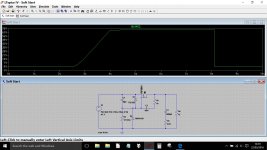
Your circuit in post #22 would ramp the voltage up but I'm not convinced its the best solution.
Thanks Mooly for simulating this!
Unfortunately I know nothing about LT Spice 🙁
- Status
- Not open for further replies.
- Home
- Amplifiers
- Power Supplies
- Inrush current limiter for DC