I never saw a diamond differential before. NP just submit it. http://www.diyaudio.com/forums/showthread.php?postid=687745#post687745
Like full complementary differential, but all the transistors are altered, N-P, P-N. Quite strange to me.
I interested in the part of "where you see the diff pairs operating push pull without limitation to the potential current they can deliver ", "This allows for the current to deliver enormous slew rates.", but advoiding this part "running an input device in Class AB is not a popular approach."
A differential (LTP) is really elegant. Only 2 transistors, but can control the whole amp and can control DC offset.
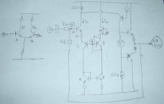
Has anyone tried this input stage? At a glance it resembles a differential, but it is not. It doesn't do "differential-ing". But it can control the whole amp and can control DC offset, like the main function of a differential.
In a differential, total current (I1+I2) will always be the same. This means if I1 is increasing, I2 will decreasing. In bipolar transistor, if I is rising or decreasing, the VBE value will also follow it.
But in this idea, if I1 rising, I2 will also rising, not decreasing. This means there is no current limiter for the input stage. Current limitation is determined elsewhere (in my drawing it is limited by CCS1 and CCS2). This also helps the input stage to be always biased.
The main fuction is done by transistor A (+C, forming 2 VBE's), in the form of changing voltage between it's base and emitor. If Y is fed by input, then X have to be fixed somewhere. X is fixed by transistor B-D, and with help of transistor C it reaches emitor of A. By VBE drops adding and substracting, automaticly the DC offset will be at ground point. I can expect this, because the current in the path I1 and I2 will always the same due to current mirror, that means all the VBE drops between left path and right path will be the same value(s)
R1 and R2 is needed there, to prevent oscilation. It may be a small valued resistor.
I'm using folded cascode for the next stage, so it perform inverting amp with gain of RF/Rin.
Funny thing is, it doesn't matter where to put the folded cascode. In both path I1 or path I2 it forms the same inverting amp.
A differential will cancel harmonic. Is this idea have the same properties (canceling harmonic), or do nothing to it, or adding harmonic? Anyone can guess what it sounds like?
Like full complementary differential, but all the transistors are altered, N-P, P-N. Quite strange to me.
I interested in the part of "where you see the diff pairs operating push pull without limitation to the potential current they can deliver ", "This allows for the current to deliver enormous slew rates.", but advoiding this part "running an input device in Class AB is not a popular approach."
A differential (LTP) is really elegant. Only 2 transistors, but can control the whole amp and can control DC offset.
Has anyone tried this input stage? At a glance it resembles a differential, but it is not. It doesn't do "differential-ing". But it can control the whole amp and can control DC offset, like the main function of a differential.
In a differential, total current (I1+I2) will always be the same. This means if I1 is increasing, I2 will decreasing. In bipolar transistor, if I is rising or decreasing, the VBE value will also follow it.
But in this idea, if I1 rising, I2 will also rising, not decreasing. This means there is no current limiter for the input stage. Current limitation is determined elsewhere (in my drawing it is limited by CCS1 and CCS2). This also helps the input stage to be always biased.
The main fuction is done by transistor A (+C, forming 2 VBE's), in the form of changing voltage between it's base and emitor. If Y is fed by input, then X have to be fixed somewhere. X is fixed by transistor B-D, and with help of transistor C it reaches emitor of A. By VBE drops adding and substracting, automaticly the DC offset will be at ground point. I can expect this, because the current in the path I1 and I2 will always the same due to current mirror, that means all the VBE drops between left path and right path will be the same value(s)
R1 and R2 is needed there, to prevent oscilation. It may be a small valued resistor.
I'm using folded cascode for the next stage, so it perform inverting amp with gain of RF/Rin.
Funny thing is, it doesn't matter where to put the folded cascode. In both path I1 or path I2 it forms the same inverting amp.
A differential will cancel harmonic. Is this idea have the same properties (canceling harmonic), or do nothing to it, or adding harmonic? Anyone can guess what it sounds like?
Attachments
Hi
what you've drawn can hardly be named 'diamond differential'.
I'd say it is not differential at all, the amp is inverting so you don't use differential, you don't substract, you add voltages by Rf and Rin.
Your input stage probalbly could be best described as common emitter, cause emitter of C is at constant voltage potential. E and F are probably redundant.
regards
Hi, Darkfenriz,
With close thermal coupling, the DC offset can be maintained closely to 0, because transistor A+C will have the same current as B+D, due to current mirror done by E+F.
If we do not place E+F, we have to put a CCS on the emitor of D, and collector of C can go straight to (-rail). But this way, the DCoffset tracking is worse, because the VBE drop of A+C is not exactly the same as VBE drop of B+D. Putting E+F ensures I1=I2, so VBE drop of A+C = VBE drop of B+D
Yes, it is not diamond differential, not a differential at all 😀. I just trying to get the merits of diamond differential but not having it's drawback, so I end up with that drawing.I'd say it is not differential at all
Yes, this one is for functioning one important aspect, to control the whole amp.Your input stage probalbly could be best described as common emitter, cause emitter of C is at constant voltage potential
This one is for another important function, that is maintaining DC offset regardless of thermal and AC condition.E and F are probably redundant.
With close thermal coupling, the DC offset can be maintained closely to 0, because transistor A+C will have the same current as B+D, due to current mirror done by E+F.
If we do not place E+F, we have to put a CCS on the emitor of D, and collector of C can go straight to (-rail). But this way, the DCoffset tracking is worse, because the VBE drop of A+C is not exactly the same as VBE drop of B+D. Putting E+F ensures I1=I2, so VBE drop of A+C = VBE drop of B+D
lumanauw,
I actually designed and built a mm phono preamp and line stage
preamp based on the input stage idea back in 1990!
I only built one channel and used a modified Jung-Didden regulator
design with it.
The sound I remember seemed very good and the regulator
improved the sound very much compared to a standard 317/337 regulator.
I built the circuit on Radio Shack experimenter plugin boards and
somehow I got the circuit to be stable with 100pf caps and
lots of ferrite beads on the supply lines. I did this with no scope
and just a Radio Shack analog meter. I tested for oscillations by
using a small fm radio nearby. I hope the local airport nearby didn't notice.
The input stage from my perspective is derived from
current conveyor toplogies. On your schematic c,d,e,f form a
first generation current conveyor(or CCI). I got the same idea
from the CCI and noticed like you the Vbe equalizing effect
due to the two current mirrors c,d and e,f. This is the idea
behind the CCI topology.
For the input stage I used jfets. At the time I use two paralled
J110's pair for the mm stage and an pn4393 pair for the main preamp.
The lower current mirrors I used a sort of Wilsonized Wilson. A four
transistor pair that cancels base current effects fairly well up to
about 10ma and with emitter resistor. The circuit was made popular by
Brett Wilson back around 1990.
Thus I had an input pair of j-fets and 8 transistors for the lower two
current mirrors.
My output was different than yours. I use an emitter follower with a common base stage
as sort of a level shifer with current and voltage gain. This feed into a current
source like yours connected to the output. I ran my stages as non-inverting with
integrators to provide dc stablity and get rid of coupling caps.
I have drawings on C sized vellum. If you wish I could make a similar schematic
using the Ltspice program I have and post it.
I considered the input circuit to be a perfect first-order circuit when using jfets.
The main problem I had was a latch up problem with turn on and circuit stability with
all those transistors in the current mirrors.
Also look at a posts I made. It uses ideas also from current conveyors.
http://www.diyaudio.com/forums/showthread.php?postid=495095#post495095
and
http://www.diyaudio.com/forums/showthread.php?postid=492286#post492286
Tom
Hi, Tom2,
I didn't realize that I draw a Current Converyor-CCI (C,D,E,F) as the final result 😀
At fist I only draw A,B,C,D, collector of C is straight to (-rail) and D is fed by CCS. D is only to make voltage reference, so this transistor is arranged as Diode.
But later I think about 0 DC offset stability is important, because I will build it as power amp with DC coupled output to the speaker, so I add E,F. The result, C,D,E,F is forming CCI, without my intention at all.
Many creative designs are limited use to preamp only. Like diamond buffer, very few makes it power amp (like SonnyA).
I'm hoping I can get good DC offset with this idea, like what can be done by usual differential input, because it is one important aspect for DC coupled output amplifier.
Can you do that?😀 I can't use simulator, but wanted to see what the harmonic pattern/ FFT looks like for my idea in #1.
Also, what is your "mm phono preamp and line stage preamp based on the input stage idea back in 1990!" looks like? those 2 links you provides seems not about it, the PassHawk still uses differential pair, the SuSyfun1a, I have to study it first, but at a glance it doesn't have 0 DC reference, and I8-I10 and I3-I4 is forming 1 CCS?
I didn't realize that I draw a Current Converyor-CCI (C,D,E,F) as the final result 😀
At fist I only draw A,B,C,D, collector of C is straight to (-rail) and D is fed by CCS. D is only to make voltage reference, so this transistor is arranged as Diode.
But later I think about 0 DC offset stability is important, because I will build it as power amp with DC coupled output to the speaker, so I add E,F. The result, C,D,E,F is forming CCI, without my intention at all.
Many creative designs are limited use to preamp only. Like diamond buffer, very few makes it power amp (like SonnyA).
I'm hoping I can get good DC offset with this idea, like what can be done by usual differential input, because it is one important aspect for DC coupled output amplifier.
I have drawings on C sized vellum. If you wish I could make a similar schematic
Can you do that?😀 I can't use simulator, but wanted to see what the harmonic pattern/ FFT looks like for my idea in #1.
Also, what is your "mm phono preamp and line stage preamp based on the input stage idea back in 1990!" looks like? those 2 links you provides seems not about it, the PassHawk still uses differential pair, the SuSyfun1a, I have to study it first, but at a glance it doesn't have 0 DC reference, and I8-I10 and I3-I4 is forming 1 CCS?
Lumanauw.
Here is the schematic of the line stage.
The mm stage is similar with an riaa feedback network and using
J110's for lower 1/f noise.
I do not claim the circuit to be perfect.
Ltspice is free and easy to use.
I'll try to do an FFT related to your circuit.
Hopefully I can make it stable.
Tom
Here is the schematic of the line stage.
The mm stage is similar with an riaa feedback network and using
J110's for lower 1/f noise.
I do not claim the circuit to be perfect.
Ltspice is free and easy to use.
I'll try to do an FFT related to your circuit.
Hopefully I can make it stable.
Tom
Attachments
Lumanauw said
Any commercial product use this kind of front end?
To my knowledge I have never seen it used. I have never
used it in a product or seen any US patents using it.
The circuit always seemed like a cool idea to me.
The attached zip file contains the front circuit like you posted
with no buffer stage or load. It has ideal current sources.
The input voltage is 1v at 1khz and the output is about 11 volts.
Also in the zip is the fft. Accuracy of the simulator????
Tom
Attachments
Hi, Tom2,
Thanks for the FFT 😀 . There seems a thing that bothers me about this CCT, that is the high-order harmonics. The harmonics below 10khz is OK, but why it also generates harmonics in frequency over 10khz, and quite big too?
At first, I hope this cct to have one merit of the X1000 SuSy. NP said that X1000 and X600 uses the SuSy like in the patent itself, that is using 2ccs in the input stage, with a resistor bridging between emitors. This SuSy doesn't use 1 differential like other X amp, but rather using 2 ccs.
Some make explenation why this topology is maintained in X1000 and X600. Usually it is about easiness to adjust current balance and DC offset with 2 ccs.
But I think with X1000 approach, it also has one important properties that is not obvious. That is the less VBE cancelation between 2 transistors in differential. I hope this topology can boost the properties of not having "VBE cancelation" and can take advantage of the sound result.
I try to make explenation about "VBE cancelation", in very simple way. If you look at the drawing in post#1, in the left side I draw a differential. Imagine it is used as an inverting amp, where the base of transistor B is grounded. The equilibrum of the junction emitors is at -0.6V, input signal at 0V, because both TR shares the same Ibias, so both has the same VBE drop.
If there is positive input signal of 0.1V, the base of TR A will be a little more positive, lets say 0.1V above ground level. This makes the TR A have VBE of 0.7V, and more current is in I1 path, I2 has less.
VBE value is tightly related to the current passing IC.
Because I2 has less current passing through it, it makes the VBE of TR2 become less than 0.6V, lets say only 0.5V. Now, if VBE of TR2 is only 0.5V, and its base is tied to ground, that makes the emitor junctions is sitting at -0.5V. If the junction is at -0.5V and the input signal is at 0.1V, in the next cycle, that makes TR1 experience only 0.6V, from first 0.7V.
The differential is inherently inhibiting TR A from having excitation, making harmonics to be canceled.
This is a very simple way from me trying to explain what I mean with "VBE cancelation". It will not acceptable in theory discussion by EE's 😀
You can see, a differential (like post #1) will always cancel harmonic, because the inherent properties of the differential itself. This harmonic cancelation will always happened in the differential, even in a non-feedback power amp. It happens because differential has only 1 ccs that has tobe shared between 2 paths.
In X1000 SuSy, this effect is less than it is in a differential. And with this input, this effect is nullified, even reversed, the topology will boost harmonics, not cancel harmonics (like in any differential).
I'm making a pcb for this topology right now, I'm using it for power amp. Hopefully, it will sound different than any amp that uses differential as input stage.
> it resembles a differential, but it is not.
Sure it is.
Because it drags an awful lot of transistors from its mid-point, it may work best with one input grounded. But the other input clearly senses difference-from-ground.
> In a differential, total current (I1+I2) will always be the same.
Not true. A fixed-current LTP is very popular, because it gives a good approximation of perfection at low cost, but this is NOT the only way.
Ponder this:
It wants to be AC-coupled (it has an input offset voltage of several volts). You can take output at either collector. You can (maybe should) ground an unused collector. The output voltage will be a function of the difference between the two input bases. If that isn't differenial, what is it?
BTW, I found this in a 1967 book and it was not new then.
Here is a quarter-baked scheme as a "balanced" mike input preamp:
An even simpler differential input is the old single input transistor, source to base, feedback to emitter. It isn't balanced or low-offset, but it sure is differential.
Sure it is.
Because it drags an awful lot of transistors from its mid-point, it may work best with one input grounded. But the other input clearly senses difference-from-ground.
> In a differential, total current (I1+I2) will always be the same.
Not true. A fixed-current LTP is very popular, because it gives a good approximation of perfection at low cost, but this is NOT the only way.
Ponder this:
An externally hosted image should be here but it was not working when we last tested it.
It wants to be AC-coupled (it has an input offset voltage of several volts). You can take output at either collector. You can (maybe should) ground an unused collector. The output voltage will be a function of the difference between the two input bases. If that isn't differenial, what is it?
BTW, I found this in a 1967 book and it was not new then.
Here is a quarter-baked scheme as a "balanced" mike input preamp:
An externally hosted image should be here but it was not working when we last tested it.
An even simpler differential input is the old single input transistor, source to base, feedback to emitter. It isn't balanced or low-offset, but it sure is differential.
lumanauw said,
There seems a thing that bothers me about this CCT, that is the high-order harmonics. The harmonics below 10khz is OK, but why it also generates harmonics in frequency over 10khz, and quite big too?
I'm guessing they are artifacts of the fft and the method I used.
Tom
Hi PRR
Hi Mr. Evil
This circuit is very interesting. I was considering using stuff like this a little time ago and came to conclusion, that this is not that good, because of voltage/current characteristics. A single transistor is well described by Eberse-Moll model assuming exponential current as a function of voltage. Now take a vintage LTP, the current is (more or less or actually) constant, one transistor is turning-on, secong off. Much distortion is cancelled. In this strange circuit nothing like distortion cancellation can ever happen, it adds distortions of both transistors.
Agreed?
best regards
You see the point 😀 It is designed so it does not cancel harmonic, but leave or add harmonic (in controlable way). I always wonder what an amp will sound if has a property of this.In this strange circuit nothing like distortion cancellation can ever happen, it adds distortions of both transistors.
You must see X600 or X1000 from Passlabs. He doesn't use differential, but 2 common emitors connected a with resistor.
Hi, PRR,
Long time no see😀
How careless of me. Off course !. Even a single common emitor sees a differential between its base voltage and emitor voltage.
Hi Darkfenriz,
There is power amp(s) that leave the harmonic by using common emitor transistor. NP's Zen and F2 is good example (F1 is differential, although). He keep digging this, there must be something different in the sound 😀
Do you have any idea, why JLH (the famous classA one) uses singleton input stage, not differential input? Is it possible that he try to advoid the differential VBE canceling effect?
> A single transistor is well described by Ebers-Moll model assuming exponential current as a function of voltage. Now take a vintage LTP, the current is (more or less or actually) constant, one transistor is turning-on, secong off. Much distortion is cancelled.
Distortion NEVER cancels completely. And the scum that remains is often more offensive than simple honest curvature.
In another world, people rave about WE-300B firebottles with no cathode resistor and no negative feedback (other than a triode's internal field effects). The THD number is huge, but almost all simple curvature, nearly no 9th or 13th harmonic such as comes out of high-feedback "distortion-cancelled" amplifiers.
Note that my plan as shown (no overall feedback) is not at all practical without that emitter resistor. That reduces distortion a lot. Interestingly, for the intended use (various input levels all trimmed to a standard output level) the distortion does not change much with gain: it depends on output level, not so much input level. I can get lower THD numbers, sure. Will it sound better? I don't know, I'm no golden-ear. The specific point was to get a "balanced" (differential) input withOUT canceling the distortion too much.
And with the NPN/PNP pairs, a little emitter resistance reduces distortion a lot. (But the real point was that in a mike-amp, this emitter resistance adds to input noise, so must be "small".)
Back to the LTP. The "distortion cancels" only for VERY small input voltages. Even 10mV of input differential will be sour. So you have to follow it with a lot of gain and wrap the whole thing in feedback. Feedback re-injects output for additional intermodulation distortion. If you keep the input levels down in the low-distortion range, there is no big difference between the LTP and a single-ended and that wacky double-single-ended plan. A lot of factors of two one way and another: the SE has twice the naked gain of the LTP so if you are doing feedback you get more feedback for your money (actually less money).
lumanauw has some points about "good" designers clinging to simple SE plans.
Hi PRR
Your point is absolutely right
but if one is looking for low distortion, the best thing to do is to use self-linearising, distortion-cancelling circuits. Of course this will cancel lower order harmonics by much higher amount than dreaded non-musical 7th or 11th or..., but it is still better idea than using feedback.
That's philosophically a bit like comparison beetwen SE and P-P.
P-P naturally cancels huge amount of even distortion, leaving odd harmonics, which one may like or not. But if I'd like to have <0.1% THD, I would go for low feedback P-P, not high feedback SE.
regards
Hi, PRR,
How low is that?
If you keep the input levels down in the low-distortion range, there is no big difference between the LTP and a single-ended and that wacky double-single-ended plan.
How low is that?
By connecting two transistors by their emitter, you can make a differential pair.
If they are of the same polarity, and the emitters see a (preferably high) resistance or a constant current source, you've got a long tail pair : it's a parallel differential pair.
If the transistors are of opposite polarity, you've got a series differential pair. One gets rid of he constant current source. I think it's sometimes called a Rush amplifier. It is interesting because it has gain without inverting.
In his famous paper in Wireless World 1977, Taylor gives the following distorsion figures :
1% for each mV at the input of a single bipolar
and thirty times less for a parallel differential pair with a 5% current mismatch.
However an overlooked problem with a differentail pair is that its distorsion components, albeit low, are depending on its DC equilibrum which continuously change in an amlifier to correct the output offset.
Is that audible ?
The distorsion components of a single transistor probably behave in a more constant manner. And amplifiers using a single active device at the input have a more simple HF behaviour.
Some people think it would be a good idea to go back to the capacitively coupled output of input stage of amplifiers (as used in tube amps) to avoid its depedance of the DC condition of the whole amplifier.
~~~~~~~ Forr
§§§
- Status
- Not open for further replies.
- Home
- Amplifiers
- Solid State
- Input stage idea