Hi, in the diagram below you can see almost a classic example of current source arrangement that is used for an input stage and the VAS as well.

My question is what is:
What is the Function of R2 and R3 resistors?
And how you decide it values (rule of thumb).
My question is what is:
What is the Function of R2 and R3 resistors?
And how you decide it values (rule of thumb).
Attachments
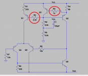
What is the Function of R2 and R3 resistors?
Improperly drawn, missing caps after them.
Must be drawn as attached, needed for additional filtering of voltage source noise.

The problem is that both current sources share the same bias feed. If one transistor hogs the current (e.g. the VAS) (in clipping for example) it upsets the current in the other stage too. For this reason the resistor (your R2) would normally be in the base of the VAS transistor.
My recommendation is to use two separate bias supplies. The cost of a couple of extra resistors, diodes and capacitors is minimal compared with the elimination of the resistor, which also has an effect on slowing down the frequency response of the transistor connected to it. (Hence the suggestion to add capacitors).
My recommendation is to use two separate bias supplies. The cost of a couple of extra resistors, diodes and capacitors is minimal compared with the elimination of the resistor, which also has an effect on slowing down the frequency response of the transistor connected to it. (Hence the suggestion to add capacitors).
Ok, I see. But what about R3? Any comments?The problem is that both current sources share the same bias feed. If one transistor hogs the current (e.g. the VAS) (in clipping for example) it upsets the current in the other stage too. For this reason the resistor (your R2) would normally be in the base of the VAS transistor.
My recommendation is to use two separate bias supplies. The cost of a couple of extra resistors, diodes and capacitors is minimal compared with the elimination of the resistor, which also has an effect on slowing down the frequency response of the transistor connected to it. (Hence the suggestion to add capacitors).
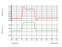
R3 is probably just to limit the current in the base of Q3. It will have the effect of slowing down the response too, so could lead to a delayed response and thereby give rise to unwanted phase shifts (i.e. potential oscillation). I tend to use passive bias networks in my current sources for that reason, but a capacitor across the base (of Q1 and Q2) should serve to control the response too. Again a pure capacitive load on a base can sometimes give rise to oscillations if there is any real or effective inductance in the leads of Q1 and Q2. Probably, it is optimum to have a capacitor with a low resistor in series to control such effects (if important). Reducing the resistance will speed up the transistor Q3 response and make overshoot less likely, which is another reason to separate the bias voltages for different current sources
Last edited:
Hi
Jony's circuit IS drawn correctly and follows Self's penny-pinching example.
BesPav's circuit is not equivalent in any way and can be ignored here.
Jony: It is best to split the current sources, which requires duplicating R4,5,6,C1 for the input stage. This makes troubleshooting any problems a lot easier and makes the function of the two circuits independent. Self added R2 for the troubleshooting ease.
The base-stops are good practise and are used far less often than theyshould be. They prevent oscillation and make circuits more stable on average. If you want to speed up the VAS current source, add 15pF from the base of Q3 to the output node of the amp before the choke.
Passive current sources have advantages and disadvantages of their own. For modern builders, active current sources allow circuit-start-up at very low voltages. There are several threads here where people have studied the different CSs always with mixed conclusions as to which is "better".
nauta: agree the current sources should be separated - see my post #3.
base stops OK up to a point. My point is that the resistor cannot be too large before it causes problems of its own.
As regards passive current sources I mentioned passive bias networks. Current sources are active. A simple pair of diodes will turn on as quickly as a transistor, and not have any issues with local feedback loops.
Hi
A resistor is passive and can be used as the current source for the diff amp or even for the VAS. The latter does not work well, evolving through being bootstrapped, then by being replaced by active CS.
You have to get to unusably high R values for a base-stop to cause problems. My comment is about the general use of base-stops.
In a current source, the higher the base-stop value, the softer the clamping action, so what you call "over-shoot" is simply the observation of soft-limiting. Soft-CS and clamping in general can provide a more musical result depending on the circuit. For example, a regulated supply for an amp will provide a more dynamic or open sound with soft current clamps rather than hard clamps.
Last edited:
Yes, a classic example of the original Miller effect- Ccb and base resistor causes a slower response.
Yes, a classic example of the original Miller effect- Ccb and base resistor causes a slower response.
Yes, if the square voltage coming from the reference of the ccs. But Ccb acting as a coupling capacitor if the collector voltage changes, and the base decoupling is not good enough (1k).
Sajti
I was considering the feedback transistor Ccb and base resistor, and you are right in assuming I applied the signal to the collector of the CCS transistor. As you mentioned, the Ccb of the CCS transistor couples to its base, so that too needs to see a low impedance.
All of which goes to show that if you want a better CCS, use a cascode stage for that too.
All of which goes to show that if you want a better CCS, use a cascode stage for that too.
Last edited:
- Status
- Not open for further replies.
- Home
- Amplifiers
- Solid State
- Input stage and VAS current sources